In industrial automation and safety systems, proximity sensors are indispensable components for detecting the presence or absence of objects without physical contact. Among their various operational modes, a common requirement from system integrators and maintenance engineers is configuring a proximity sensor for a continuously illuminated state. This article delves into the technical principles, methodologies, and critical considerations for achieving and maintaining a proximity sensor in a constantly "ON" or illuminated condition, focusing primarily on inductive and capacitive types prevalent in electrical engineering.
Fundamentally, a standard proximity sensor is designed to switch its output state when a target enters its sensing field. The illuminated indicator, typically an LED, is tied to this output state. For it to remain continuously lit, the sensor's output must be held in an active state. The most straightforward method is to place a valid target within the sensor's nominal sensing range permanently. This could be a metal object for an inductive sensor or a material with suitable dielectric properties for a capacitive sensor. However, this static physical solution is often impractical in dynamic industrial environments where the sensor's primary function is to detect moving targets.
A more sophisticated approach involves manipulating the sensor's wiring or internal logic. For a 3-wire DC sensor (Brown/+V, Blue/0V, Black/Output), the continuous illumination of its indicator LED usually signifies that the output transistor (PNP or NPN) is in a conducting state. To force this, one can create an electrical condition that mimics a detected target. For a PNP (sourcing) sensor, this means the output wire (Black) must be continuously providing the supply voltage. This can be artificially achieved by bypassing the sensor's internal switching logic. Warning: This typically requires internal circuit modification, such as jumpering specific test points or components on the sensor's PCB, which voids warranties, may violate safety standards, and is not recommended without deep understanding of the specific sensor's design. It permanently alters the sensor's functionality, rendering it incapable of normal switching operation.
A safer and reversible alternative is to use the sensor in conjunction with external control logic. For instance, the sensor's output can be fed into a Programmable Logic Controller (PLC) or a latching relay circuit. The PLC program can be written to ignore the sensor's actual signal and instead continuously assert a "high" or "ON" signal to the downstream indicator circuit, effectively keeping the illumination LED lit regardless of physical target presence. This method preserves the sensor's original detection capability for the PLC's internal logic while separately driving the required visual state.
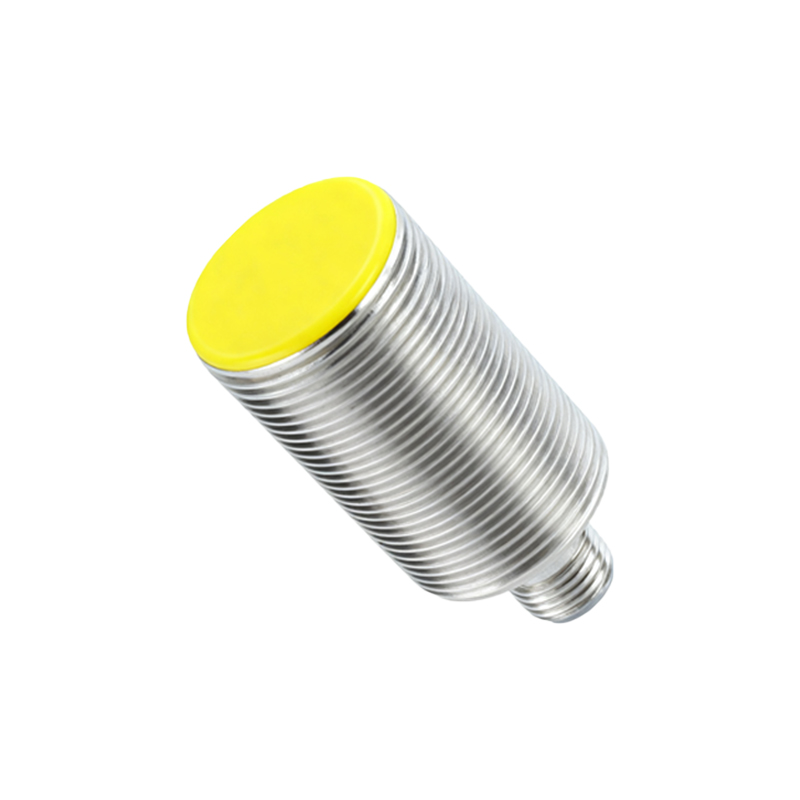
Another consideration is the sensor's built-in output mode. Some programmable sensors offer a "Light ON" or "Dark ON" mode selection. In "Dark ON" mode, the output is active (and the LED is lit) when no target is detected. Therefore, to keep the LED lit, one would simply ensure no target enters the sensing field. Conversely, selecting "Light ON" mode and then permanently placing a target in range would achieve the same continuous illumination. Always consult the sensor's datasheet for configurable output modes.
Environmental and electrical factors are crucial. Ensure the sensor is operating within its specified voltage range. Undervoltage can cause erratic behavior, while overvoltage may damage the unit. Electrical noise from nearby motors or frequency drives can induce false signals, potentially causing unwanted illumination changes. Proper shielding, grounding, and the use of filters are essential in electrically noisy environments. Additionally, for inductive sensors, the characteristics of the permanent target (material, size, shape) must meet the sensor's specifications to guarantee reliable and stable activation. Mild steel is the standard reference; other metals like aluminum or stainless steel have reduced sensing distances and may require recalibration or a different sensor type.
Thermal management is often overlooked. A sensor forced into a continuously active state, especially through internal modifications, may experience higher than normal current draw in its output stage, leading to increased junction temperatures. Over time, this can accelerate component aging and lead to premature failure. Always verify that the operational configuration does not exceed the sensor's maximum power dissipation ratings.
In summary, achieving a continuously illuminated proximity sensor can be accomplished through several tiers of intervention: the simple physical method (permanent target), the external control method (using a PLC or relay to drive the indicator), or the internal hardware modification method (not recommended for general practice). The choice depends on the application's requirements for reversibility, safety compliance, and the need to retain the sensor's original detection function. Prioritize methods that maintain system integrity and adhere to relevant electrical safety standards like IEC 60947-5-2. Always reference the manufacturer's specific technical documentation before implementing any configuration changes.