Explosion-proof proximity sensors are critical components in hazardous industrial environments where flammable gases, vapors, or dusts may be present. Proper wiring is not merely a matter of functionality; it is a fundamental safety requirement to prevent ignition sources and ensure reliable operation. This guide provides a comprehensive overview of wiring diagrams and best practices for installing these specialized sensors.
Understanding the core principle is essential. An explosion-proof enclosure is designed to contain any ignition that might occur within its housing, preventing it from reaching the external hazardous atmosphere. The wiring connections, both at the sensor and throughout the conduit system, must maintain this integrity. The most common types of explosion-proof proximity sensors include inductive (for metals) and capacitive models, typically with a DC 3-wire configuration (PNP or NPN) or a 2-wire AC/DC configuration.
A standard wiring diagram for a 3-wire DC sensor will clearly label the terminals: Brown wire (or +V): This is the positive power supply lead, usually connecting to a 10-30V DC source. Blue wire (or 0V): This is the negative or common return lead. Black wire (or OUT): This is the switched output signal lead. For a PNP sensor (sourcing), the black wire provides positive voltage to the load when the target is detected. For an NPN sensor (sinking), it provides a path to ground. The diagram will also prominently show the grounding symbol, indicating the mandatory connection of the sensor's ground terminal or the conduit's grounding lug to a verified earth ground. This is non-negotiable for safety and shielding.
The wiring diagram for a 2-wire sensor is simpler, showing two leads that are connected in series with the load and power supply. Polarity must be observed for DC versions. Crucially, any diagram for an explosion-proof application will include notes on the required conduit and cable glands. These must be certified explosion-proof fittings (e.g., with an Ex d rating) that maintain the seal of the enclosure. The diagram often specifies a torque value for the gland's compression nut to ensure a proper seal.
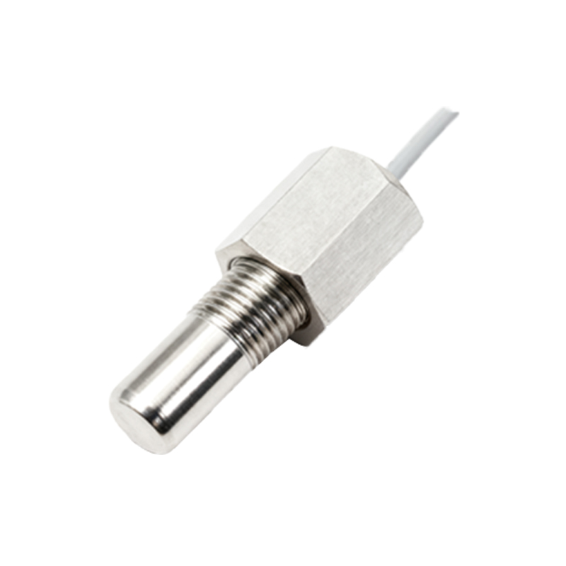
Key steps for safe installation based on the wiring diagram include: First, always de-energize the circuit and verify a zero-energy state using appropriate locked-out/tagged-out (LOTO) procedures in the safe area before beginning any work. Select and install the correct certified cable glands onto the sensor's entry ports. Thread the approved, properly sized cables through the conduit and glands. Strip the wires to the length specified by the terminal block or connector. Connect the wires firmly to the correct terminals as per the diagram, ensuring no loose strands are present. Tighten the cable glands to the manufacturer's specified torque to complete the explosion-proof seal. Finally, before powering, perform a continuity and insulation resistance test to check for shorts or grounds.
Common pitfalls to avoid are: Using standard cable glands instead of certified explosion-proof versions. This compromises the entire safety system. Over-tightening or under-tightening the conduit connections, which can damage the seal. Incorrectly identifying PNP vs. NPN wiring, leading to controller input damage. Neglecting proper grounding, which can cause erratic operation and pose an electrostatic discharge risk. Failing to follow the specific torque specifications for the sensor's blanking plugs or terminal compartment covers.
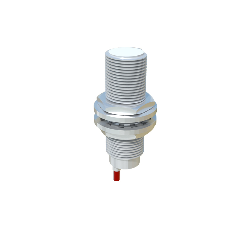
Always consult the manufacturer's specific wiring diagram and installation manual for the exact model you are using. Regulations such as the NEC (NFPA 70), IECEx, or ATEX directives provide the governing standards. Remember, correct interpretation and execution of the explosion-proof proximity sensor wiring diagram is a critical engineering task that ensures both operational performance and the paramount goal of personnel and facility safety in hazardous locations.