Laser sensors are critical components in modern industrial automation, offering high precision for measurement, detection, and positioning tasks. Proper calibration and debugging are essential to ensure optimal performance and system reliability. This tutorial provides a systematic approach for engineers to set up, calibrate, and troubleshoot common laser sensor issues.
Before beginning the calibration process, ensure all safety protocols are followed. Disconnect power to the system and verify that the laser emission is Class 1 or Class 2, as per IEC 60825-1 standards, to prevent eye damage. Wear appropriate protective equipment. Mount the sensor securely on a stable surface, minimizing vibrations that could affect readings. Check the datasheet for the sensor's specific mounting orientation, operating voltage, and environmental limits regarding temperature, humidity, and ambient light.
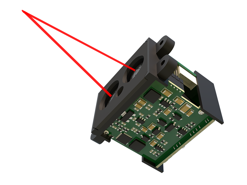
The first calibration step involves aligning the sensor. Power on the sensor and connect it to a monitoring device, such as a PLC interface or dedicated controller software. Position the target object at the desired reference distance. Using the sensor's teach function or configuration software, set this position as the zero or reference point. For analog output sensors, map the minimum and maximum detection distances to the corresponding voltage or current output range (e.g., 0-10V or 4-20mA). For digital sensors, set the switching thresholds precisely. Ensure the sensor's response time is configured to match the application speed without causing false triggers.

Environmental interference is a common challenge. Strong ambient light, particularly from other lasers or infrared sources, can saturate the sensor's receiver. Use sensors with modulated laser light or polarization filters to mitigate this. For dusty or foggy environments, select sensors with higher output power and ensure lenses are kept clean. Electrical noise from motors or variable frequency drives can disrupt signals. Use shielded cables, proper grounding, and separate conduits for power and signal lines. Ferrite cores on cables near noise sources can further reduce electromagnetic interference.
Troubleshooting typically starts with symptom analysis. If the sensor provides no output, verify power supply voltage and polarity. Check all cable connections for breaks or loose terminals. Inspect the indicator LEDs; a missing power LED suggests a wiring issue, while a constant alarm LED may indicate a fault code described in the manual. Erratic or inconsistent measurements often stem from alignment drift, dirty optics, or environmental factors. Re-align the sensor and clean the lens with a soft, lint-free cloth and approved cleaner. For analog sensors, use a multimeter to verify the output signal stability against the expected range.

Advanced diagnostics may involve oscilloscope analysis of the output waveform to detect noise or signal distortion. If the sensor's response time is too slow, adjust the filtering settings, but be cautious not to make it overly sensitive to noise. For multi-sensor systems, ensure they are not optically interfering with each other; stagger their operating frequencies if adjustable. Always document calibration settings, including teach points, output ranges, and filter values, for future maintenance and replication.
Regular maintenance schedules are crucial. Periodically verify calibration against a master reference target. Log performance data to identify gradual degradation. Firmware updates from the manufacturer can resolve known bugs or improve performance, so check for updates periodically. By following these structured procedures, engineers can ensure laser sensors deliver precise, reliable data, minimizing downtime and maintaining high-quality automation processes. Remember, consulting the specific manufacturer's manual is always recommended, as procedures can vary between models and brands.