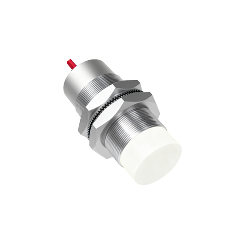
In industrial automation and control systems, proximity sensors play a critical role in detecting the presence or absence of objects without physical contact. Among various types, six-wire proximity sensors are widely used due to their versatility, offering both normally open (NO) and normally closed (NC) outputs along with separate power supply connections. This article provides a comprehensive guide to wiring six-wire proximity sensors, ensuring reliable operation and optimal performance in demanding environments.
Understanding the six-wire configuration is essential for proper installation. Typically, the wires are color-coded or labeled as follows: brown (V+ or power supply positive), blue (V- or power supply negative), black (NO output), white (NC output), and often gray and pink for additional functions like diagnostic or enable signals, depending on the manufacturer. The brown and blue wires connect to the DC power source, usually ranging from 10-30V DC, to energize the sensor. The black wire provides the NO output, meaning it closes the circuit when an object is detected, while the white wire offers the NC output, which opens the circuit upon detection. This dual-output design allows for flexible integration into control logic, such as PLCs or relays, enabling both safety and operational functions.
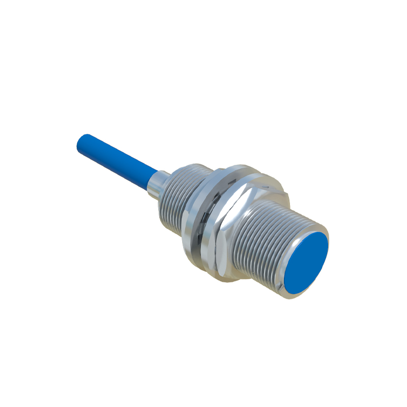
To wire a six-wire proximity sensor correctly, start by verifying the sensor specifications from the datasheet, including voltage ratings, output types (e.g., PNP or NPN switching), and current limits. For a standard DC setup, connect the brown wire to the positive terminal of the power supply and the blue wire to the negative terminal. Ensure proper grounding to minimize electrical noise, which can cause false triggers. Next, link the black (NO) and white (NC) wires to the load devices. For instance, in a PNP configuration, the black wire can be connected to a PLC input module to signal detection, while the white wire might be used for an alarm circuit that activates when no object is present. Always use shielded cables for long runs to prevent interference, and secure connections with appropriate terminals to avoid loose contacts.
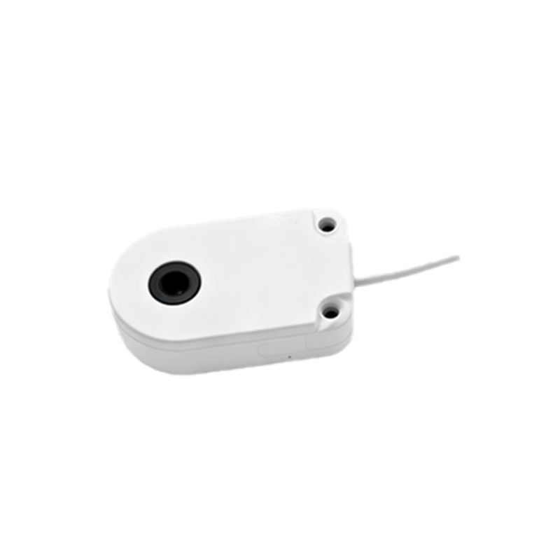
Common pitfalls in wiring include incorrect polarity, which can damage the sensor, or mixing up NO and NC outputs, leading to logic errors in the control system. To troubleshoot, use a multimeter to check voltage levels and continuity. If the sensor fails to detect objects, verify power supply stability and inspect for environmental factors like metal debris or excessive vibration. Regular maintenance, such as cleaning the sensing face and checking cable integrity, enhances longevity. In applications with high electromagnetic interference, consider using filters or ferrite cores on the cables.
Best practices for six-wire proximity sensor installation involve planning the layout to avoid cross-talk between multiple sensors and ensuring adequate clearance from moving parts. Follow industry standards, such as IEC 60947-5-2, for safety and compatibility. By mastering these wiring techniques, engineers can optimize sensor performance, reduce downtime, and improve system reliability in automation projects.