Cylindrical proximity sensors are ubiquitous in industrial automation, serving as critical components for position detection, object counting, and machine safety. Understanding their internal construction is vital for maintenance, troubleshooting, and even custom modifications. This guide provides a detailed, professional method for disassembling a standard inductive cylindrical proximity sensor. Prior to any disassembly, ensure the sensor is completely disconnected from its power source and removed from the installation. Always wear appropriate personal protective equipment (PPE), such as safety glasses and gloves.
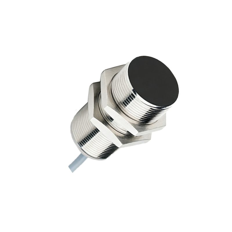
The first step involves a thorough external inspection. Note the sensor's model number, specifications (e.g., sensing distance, output type), and any visible damage. Standard components include the sensing face, the threaded metal barrel, a hex nut, and the cable or connector housing. For sensors with an integral cable, inspect the cable entry point for strain relief integrity.
Begin disassembly by securing the sensor in a soft-jawed vise to prevent damage to the threaded barrel. The goal is to separate the main housing. Typically, the front sensing head is a press-fit or threaded assembly onto the main barrel. Using appropriate tools—often a small strap wrench or non-marring pliers—carefully attempt to rotate the sensing head counterclockwise. Apply steady, moderate force. Some manufacturers use thread-locking compounds; applying gentle heat with a heat gun (avoiding direct flame) can soften this adhesive.
Once the sensing head is removed, the internal core assembly becomes accessible. You will typically see a coil wound around a ferrite core, potted in epoxy or another compound for environmental protection and mechanical stability. This potting material is challenging to remove without damaging the coil. For analysis purposes, carefully note the coil's connections, which lead to the sensor's electronics.
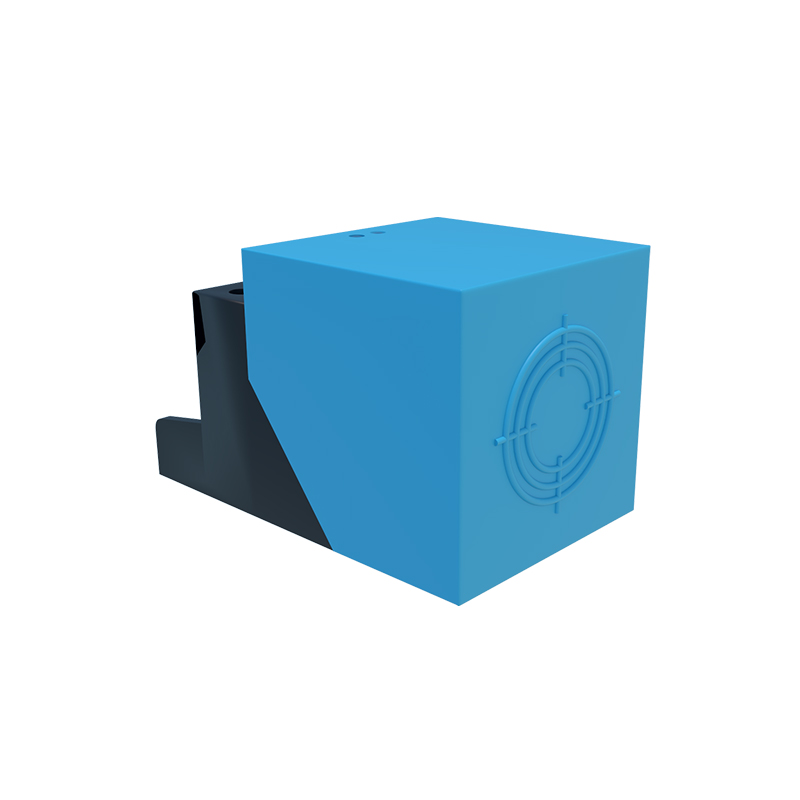
The next section is the rear housing, which contains the oscillator, amplifier, and output switching circuitry. This is usually a separate plastic or metal capsule threaded or snapped into the main barrel. Unscrew or carefully pry this open. Inside, a small printed circuit board (PCB) will be visible. Observe the connections between the coil wires and the PCB, often soldered or connected via terminals. Document the PCB layout and component identification if possible.
Handling the PCB requires extreme caution. Components are typically surface-mounted and sensitive to electrostatic discharge (ESD). Use an antistatic wrist strap. The output stage—whether NPN, PNP, or analog—will be clearly marked on the PCB. Note any adjustment potentiometers for sensing range or hysteresis, if present.
Reassembly is essentially the reverse process. Ensure all seals, O-rings (if any), and gaskets are correctly repositioned to maintain the sensor's IP (Ingress Protection) rating. Reapply thread-locking compound as needed and torque components to manufacturer specifications to ensure proper mechanical and environmental sealing.
This disassembly process reveals the robust yet delicate nature of these devices. The potting material protects against vibration, coolant, and metal chips, making non-destructive full disassembly difficult. Therefore, this exercise is primarily for educational, diagnostic, or repair purposes where a replacement sensor is not immediately available. Always consult the manufacturer's technical data before attempting any disassembly that might void warranties or compromise safety certifications. Understanding these internal structures deepens an engineer's ability to select, integrate, and maintain these essential automation components effectively.