Proximity sensor switches are widely used in industrial automation, machinery, and safety systems to detect the presence or absence of an object without physical contact. Proper wiring is crucial for ensuring reliable operation, preventing damage to the sensor or connected equipment, and maintaining safety standards. This guide provides a step-by-step overview of how to wire a proximity sensor switch, covering common types, wiring configurations, and best practices.
First, identify the type of proximity sensor switch you are working with. The two main categories are inductive and capacitive sensors, each suited for different materials. Inductive sensors detect metallic objects, while capacitive sensors can detect both metallic and non-metallic materials. Additionally, sensors are classified by their output type: NPN (sinking) or PNP (sourcing), and normally open (NO) or normally closed (NC) configurations. Check the sensor’s datasheet or labeling to confirm these specifications, as they determine the wiring approach.
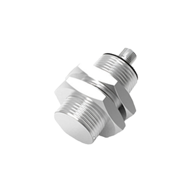
Before starting, ensure all power sources are disconnected to prevent electrical shock or short circuits. Gather the necessary tools, including wire strippers, screwdrivers, and appropriate cables. Most proximity sensors have three wires: brown (positive), blue (negative), and black (output). Some models may include a white wire for additional functions like timing or diagnostics.
For a basic three-wire DC sensor, follow these steps:
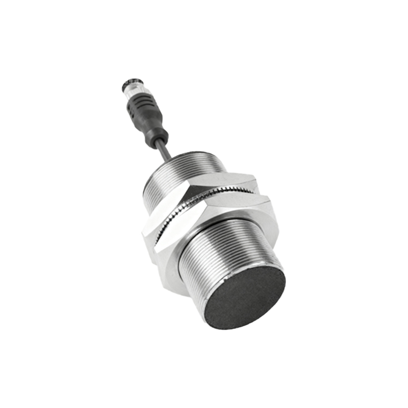
1. Connect the brown wire to the positive terminal of the power supply (typically +24V DC).
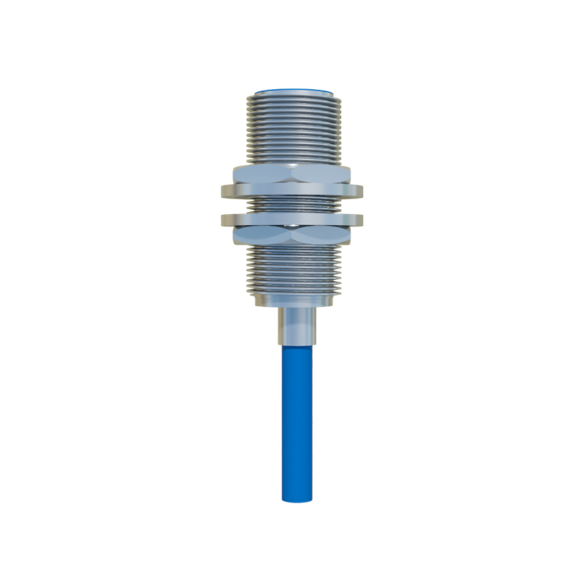
2. Connect the blue wire to the negative terminal (0V or ground).
3. Connect the black wire to the load, such as a programmable logic controller (PLC) input, relay, or indicator light.
4. If using a PNP sensor, the black wire provides a positive output when activated; for an NPN sensor, it provides a negative output. Ensure the load is compatible with the sensor’s output type.
In a two-wire AC sensor, wiring is simpler: one wire connects to the live AC voltage, and the other to the load. However, these sensors may have higher leakage current, which can affect sensitive loads. Always verify voltage ratings—common options include 10-30V DC for DC sensors and 20-250V AC for AC sensors.
Shielded cables are recommended for long-distance wiring or environments with electromagnetic interference (EMI). Ground the shield at one end to avoid ground loops. Keep sensor cables away from power lines and motor drives to reduce noise. Additionally, maintain proper clearance between sensors and metal surfaces to prevent false triggering.
After wiring, perform a functional test. Reconnect power and bring a target object within the sensor’s sensing range. Verify that the output activates correctly—for example, a PLC input LED should light up. If the sensor fails to respond, double-check connections, power supply polarity, and sensor alignment. Consult the manufacturer’s troubleshooting guide if issues persist.
Regular maintenance includes inspecting wires for damage, cleaning the sensor face, and testing performance periodically. Proper installation not only extends the sensor’s lifespan but also enhances system reliability. By following these guidelines, you can wire proximity sensor switches efficiently and safely, ensuring optimal performance in automation applications.