In industrial automation and control systems, proximity sensors play a critical role in detecting the presence or absence of objects without physical contact. Among various types, the 24V two-wire proximity sensor is widely favored for its simplicity, reliability, and ease of integration. This article provides a comprehensive guide to understanding the wiring diagram, installation principles, and best practices for 24V two-wire proximity sensors, ensuring optimal performance in your applications.
A 24V two-wire proximity sensor operates on a 24V DC power supply, which is standard in many industrial environments due to its safety and compatibility with PLCs (Programmable Logic Controllers) and other control devices. Unlike three-wire sensors that have separate power, ground, and signal wires, the two-wire version combines power and signal functions into two wires, simplifying wiring and reducing costs. The basic principle involves the sensor drawing a small leakage current when idle and increasing current flow when an object is detected, thereby signaling the connected control system.
The wiring diagram for a 24V two-wire proximity sensor is straightforward. It consists of two terminals: one for connecting to the positive side of the 24V DC power supply and the other for connecting to the load (e.g., a PLC input module or relay). Here’s a step-by-step breakdown:
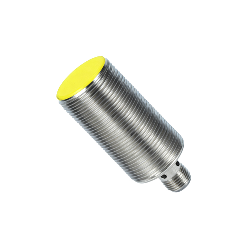
1. Power Supply Connection: Connect the positive terminal of the 24V DC power source to one wire of the sensor. Ensure the power supply is rated for 24V DC and can handle the sensor’s current consumption, typically ranging from 1 to 3 mA in idle state and up to 20-30 mA during activation.
2. Load Connection: Connect the other wire of the sensor to the input of the load device. For instance, if using a PLC, this wire goes to the designated input point. The load then connects back to the negative terminal of the power supply, completing the circuit.
3. Polarity Considerations: Most 24V two-wire proximity sensors are polarity-insensitive, meaning they can be wired in either direction without damage. However, always refer to the manufacturer’s datasheet, as some models may require specific polarity for proper operation.
4. Shielding and Protection: In environments with electrical noise or interference, use shielded cables and ground the shield at one end to prevent false triggering. Additionally, install fuses or circuit breakers in the power line to protect against short circuits.
When installing a 24V two-wire proximity sensor, follow these best practices to ensure reliability:
- Mounting Position: Place the sensor perpendicular to the target object’s approach direction for maximum sensitivity. Maintain the specified sensing distance, usually a few millimeters to 20 mm, depending on the model.
- Environmental Factors: Avoid mounting near sources of heat, vibration, or corrosive substances. For harsh conditions, choose sensors with appropriate IP (Ingress Protection) ratings, such as IP67 for dust and water resistance.
- Testing and Calibration: After wiring, power on the system and test the sensor by bringing a target object within range. Use a multimeter to verify voltage drops or current changes, ensuring the sensor switches correctly. Adjust the mounting if necessary to avoid false detections.
Common applications of 24V two-wire proximity sensors include object detection in conveyor systems, position sensing in machinery, and safety interlocks in automated equipment. Their two-wire design reduces wiring complexity, making them ideal for space-constrained installations. However, note that these sensors may have a higher residual current compared to three-wire versions, which can affect low-power circuits; always check compatibility with your control system.
In summary, the 24V two-wire proximity sensor offers a cost-effective and efficient solution for non-contact detection in industrial settings. By understanding the wiring diagram and adhering to installation guidelines, you can enhance system performance and minimize downtime. For specific models, consult the manufacturer’s documentation to tailor the setup to your needs.