In industrial automation and control systems, proximity sensors play a critical role in detecting the presence or absence of objects without physical contact. Among various configurations, the 4-wire proximity sensor is widely favored for its versatility, combining both normally open (NO) and normally closed (NC) outputs in a single device. This guide provides a comprehensive overview of the 4-wire connection methodology, ensuring reliable operation in demanding environments.
A typical 4-wire proximity sensor consists of two power supply wires and two output wires. The power supply wires, usually labeled as brown (positive) and blue (negative), connect to a DC power source, commonly 10-30 VDC. The brown wire is linked to the positive terminal, while the blue wire is connected to the negative or ground terminal. Proper power supply connection is essential for sensor functionality, as incorrect polarity can damage the internal circuitry. The remaining two wires, often black and white, represent the output signals. The black wire typically serves as the NO output, meaning it conducts current when an object is detected within the sensing range. Conversely, the white wire functions as the NC output, conducting current when no object is present and interrupting the circuit upon detection. This dual-output design allows for flexible integration into control systems, enabling both direct and inverse logic operations.
When wiring a 4-wire proximity sensor, adherence to electrical standards and safety protocols is paramount. Begin by verifying the sensor's specifications, including voltage rating, sensing distance, and output type (e.g., PNP or NPN). For PNP sensors, the output wires switch the positive voltage, whereas NPN sensors switch the negative side. In a standard PNP configuration, connect the brown wire to the positive DC supply, the blue wire to the negative supply, and the black and white wires to the load devices, such as PLC input modules, relays, or indicators. Ensure that the load is compatible with the sensor's current and voltage ratings to prevent overheating or failure. For instance, if the sensor has a maximum load current of 200 mA, the connected device should operate within this limit. Use shielded cables in environments with electromagnetic interference (EMI) to minimize signal noise, and secure all connections with appropriate terminals to avoid loose contacts.
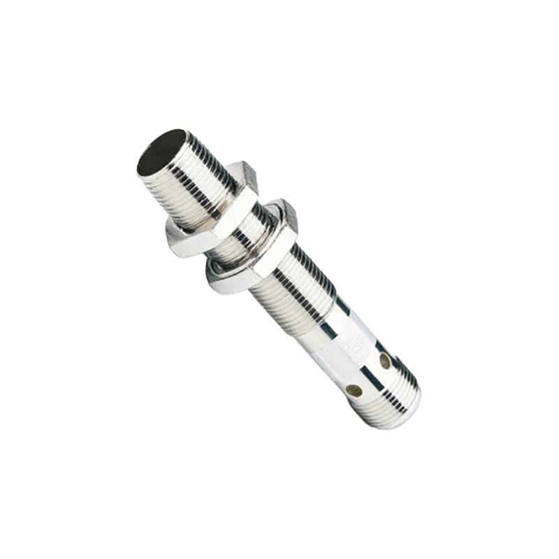
Practical applications of 4-wire proximity sensors span across manufacturing, packaging, and robotics. In conveyor systems, they detect product positions to trigger sorting mechanisms, with the NO output activating a diverter arm and the NC output monitoring for jams. In safety circuits, the NC output can be integrated into emergency stop loops, ensuring immediate shutdown if an object is detected in a hazardous zone. Troubleshooting common issues involves checking power supply stability, inspecting wiring for shorts or breaks, and verifying sensor alignment. A multimeter can be used to measure voltage at the output wires; for a PNP sensor, the black wire should show supply voltage when activated, while the white wire should show voltage when deactivated. Regular maintenance, including cleaning the sensing face and testing response times, enhances longevity and accuracy.
In summary, mastering the 4-wire proximity sensor connection enhances system reliability and flexibility. By following correct wiring practices and understanding output behaviors, engineers can optimize automation processes, reduce downtime, and ensure safe operation. Always refer to manufacturer datasheets for model-specific details, as wire colors and functions may vary. With proper installation, these sensors provide robust, non-contact detection solutions for diverse industrial challenges.