Cylindrical proximity sensors are indispensable components in modern industrial automation, offering non-contact detection of metallic and, in some cases, non-metallic objects. Their robust cylindrical housing, typically constructed from nickel-plated brass, stainless steel, or PBT plastic, provides excellent resistance to mechanical stress, cutting fluids, and coolants commonly found in harsh manufacturing environments. This guide details their operational principles, key specifications, selection criteria, and application best practices.
Operating Principle and Types
The core function is based on the disruption or alteration of an electromagnetic field. The primary technologies are Inductive, Capacitive, and Ultrasonic. Inductive sensors are the most prevalent for cylindrical designs, detecting ferrous and non-ferrous metals without physical contact. They generate an oscillating electromagnetic field from a coil in the sensor's face. When a metallic target enters this field, eddy currents are induced, causing a change in oscillation amplitude. This change is detected by the sensor's circuitry, triggering a solid-state output switch. Capacitive cylindrical sensors can detect both metallic and non-metallic materials (plastics, wood, liquids) by sensing changes in capacitance. Ultrasonic variants use sound waves for detection, suitable for various materials and capable of distance measurement.
Key Technical Specifications
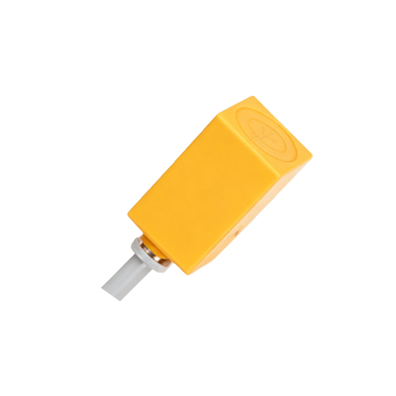
Understanding datasheet parameters is critical for correct selection.
Sensing Distance (Sn): The nominal operating distance. For a standard M18 inductive sensor, this is often 5mm or 8mm. A safety factor (typically 70-80% of Sn) is applied in practice to account for temperature fluctuations and supply voltage variations.
Hysteresis: The difference between the switch-on and switch-off points, expressed as a percentage of Sn. This prevents output chattering when a target is at the sensing limit.
Output Configuration: Common configurations include NPN (sinking) and PNP (sourcing) transistor outputs. NPN is prevalent in Asia and North America, while PNP is common in Europe. 2-wire AC/DC, 4-wire combo (two PNP + two NPN), and analog (4-20mA, 0-10V) outputs are also available.
Shielding (Unshielded/Shielded): Shielded (flush-mountable) sensors can be embedded in metal without affecting performance. Unshielded (non-flush) sensors offer a longer sensing range but require clearance from surrounding metal.
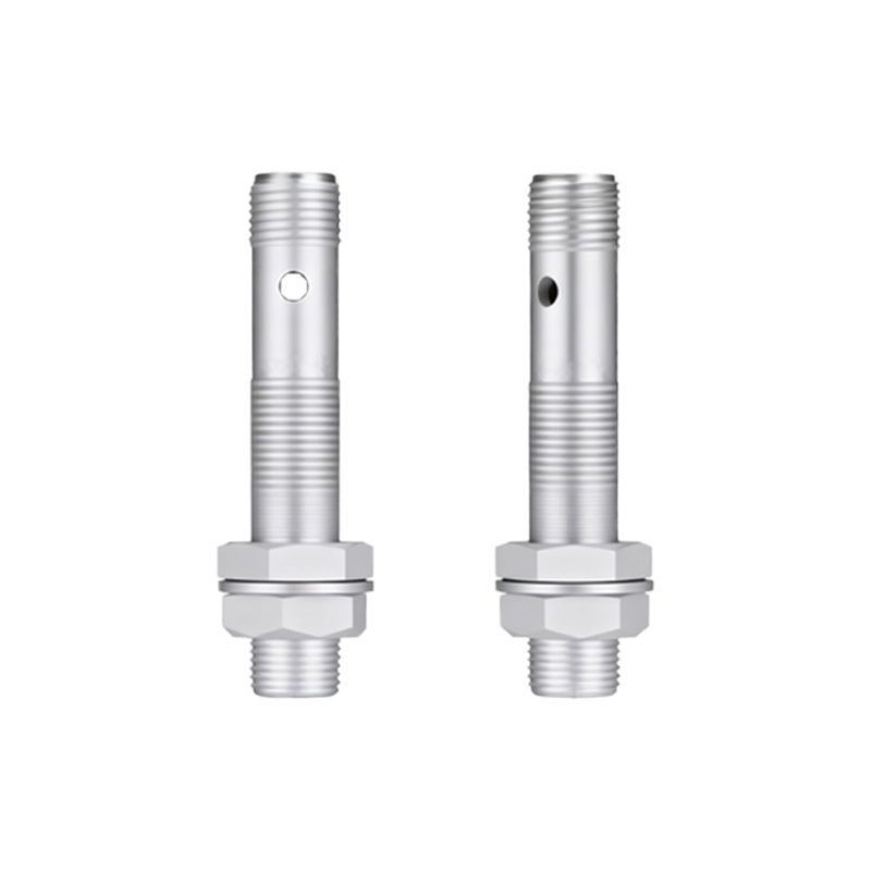
Frequency Response: The maximum number of switching cycles per second, crucial for high-speed counting or positioning applications.
IP Rating: Ingress Protection rating (e.g., IP67, IP69K) defines protection against dust and liquids. IP67 allows temporary immersion, while IP69K withstands high-pressure, high-temperature washdowns.
Connection Style: Integral cable (fixed or flexible) or quick-disconnect (plug-in) versions. Plug-in styles simplify maintenance and replacement.
Selection Guidelines
1. Target Material: For metals only, choose inductive. For all materials including glass, powder, or liquid, select capacitive or ultrasonic.
2. Required Sensing Range: Choose a sensor with a rated distance (Sn) 20-30% greater than the maximum required application gap.
3. Installation Environment: Consider temperature extremes, presence of chemicals, welding spatter, or high-pressure washdown. Stainless steel housings and PTFE-coated faces are ideal for aggressive environments.
4. Electrical Compatibility: Match the output type (NPN/PNP) and voltage range (10-30VDC, 20-250VAC) with your PLC or control system input module. Ensure the load current does not exceed the sensor's maximum rating.
5. Physical Size Constraints: Standard diameters include M4, M5, M8, M12, M18, and M30. Ensure adequate space for mounting and any required side or rear clearance for unshielded models.
Application Examples and Wiring
Typical applications include position sensing of machine tool slides, end-of-stroke detection on cylinders, jam detection in conveyors, and part presence verification in assembly fixtures. For wiring a 3-wire DC sensor: Connect the brown wire (+V), blue wire (0V/common), and the black wire (load output) to the PLC input. Always refer to the manufacturer's datasheet for the precise wiring diagram. Incorporate reverse polarity and short-circuit protection where necessary.
Installation and Troubleshooting Tips
Ensure the target approaches the sensor face perpendicularly for maximum range and repeatability.
Maintain a stable power supply; voltage ripple can cause erratic operation.