Proximity sensor modules are widely used in industrial automation, robotics, and safety systems due to their non-contact detection capabilities. Understanding the correct wiring of these modules is crucial for ensuring reliable operation and preventing damage to both the sensor and the connected control system. This guide provides a detailed wiring diagram explanation for typical inductive and capacitive proximity sensor modules, covering common configurations and practical considerations.
Most proximity sensor modules consist of three or four wires, with color coding that may vary by manufacturer. The standard wiring for a three-wire DC sensor includes:
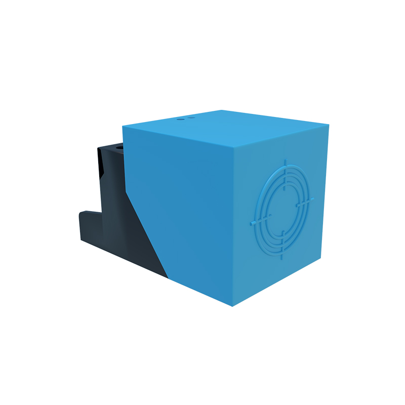
- Brown wire: Connected to the positive DC supply voltage (typically 10-30V DC).
- Blue wire: Connected to the negative DC supply or ground.
- Black wire: The output signal line, which switches to supply voltage (PNP) or ground (NPN) when an object is detected.

For a four-wire DC sensor, an additional white wire is often provided for a complementary output or diagnostic function. Always refer to the manufacturer's datasheet for specific wire assignments, as colors can differ.
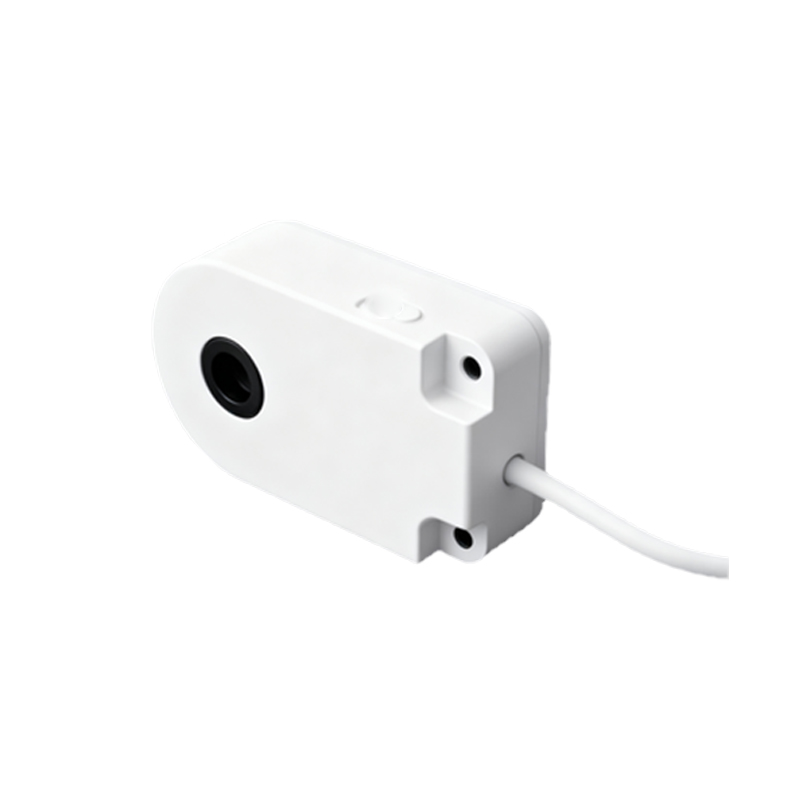
Wiring Diagram for PNP (Sourcing) Configuration:
In a PNP configuration, the output wire provides positive voltage when activated. Connect the brown wire to the DC positive terminal, the blue wire to DC negative, and the black wire to the PLC input or load. The load is then connected between the black wire and ground. This setup is common in European and modern global systems.
Wiring Diagram for NPN (Sinking) Configuration:
In an NPN configuration, the output wire sinks current to ground when activated. Connect the brown wire to DC positive, the blue wire to DC negative, and the black wire to the load. The other side of the load is connected to DC positive. This configuration is frequently used in North America and Asia.
When integrating with a programmable logic controller (PLC), ensure the sensor's output type (PNP or NPN) matches the PLC input specifications. Mismatched wiring can lead to malfunction or hardware damage. For two-wire AC sensors, connect one wire to the AC line and the other to the load, observing voltage and current ratings.
Shielded cables are recommended for long-distance wiring or electrically noisy environments to prevent electromagnetic interference. Maintain proper cable routing, avoiding parallel runs with high-voltage power lines. Always implement protective measures such as fuses or circuit breakers in the supply line, and consider using surge suppressors for sensors in areas prone to voltage spikes.
Testing the wiring involves applying power and verifying the output state with and without a target object. Use a multimeter to check voltage levels at the output wire. For smart sensors with diagnostic LEDs, observe the indicator lights for normal operation. Regular maintenance includes inspecting connections for corrosion, ensuring tight terminals, and verifying insulation integrity.
By following these wiring guidelines and referring to the specific module's documentation, engineers can achieve stable and accurate proximity sensing in diverse applications, from conveyor belt object detection to machine safety interlocks.