In the realm of industrial automation, proximity sensors are indispensable components for non-contact detection of metallic and non-metallic objects. Among the various configurations available, DC 3-wire cylindrical proximity sensors stand out for their reliability, ease of installation, and robust performance in demanding environments. This article delves into the technical intricacies, operational principles, selection criteria, and application best practices for these critical devices.
Operational Principle and Core Technology
DC 3-wire cylindrical proximity sensors operate primarily on the inductive sensing principle. The sensor's face contains an oscillator circuit that generates a high-frequency electromagnetic field. When a metallic target enters this field, eddy currents are induced on the target's surface. This causes a change in the oscillation amplitude, which is detected by a threshold circuit. The circuit then triggers a solid-state switch (typically an NPN or PNP transistor) in the output stage, changing the state of the sensor. The "3-wire" designation refers to the wiring configuration: one wire for DC power supply positive (brown), one for DC power supply negative (blue), and one for the output signal (black). This design allows for a simple connection to programmable logic controllers (PLCs) and other control systems, providing a clear switching signal without the need for an external load resistor, which is common in 2-wire designs.
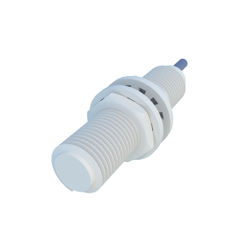
Key Advantages of the Cylindrical Form Factor
The cylindrical housing, often standardized with M8, M12, M18, or M30 threaded barrels, offers significant benefits. This shape provides excellent mechanical strength and facilitates easy installation into drilled and tapped holes, with the threaded body allowing for precise adjustment of sensing distance. The design is inherently resistant to torsional forces and simplifies sealing, making most models compliant with IP67 or IP69K ratings for protection against dust and high-pressure water jetting. The compact and symmetrical form allows for installation in tight spaces and from any radial orientation, offering flexibility in machine design.
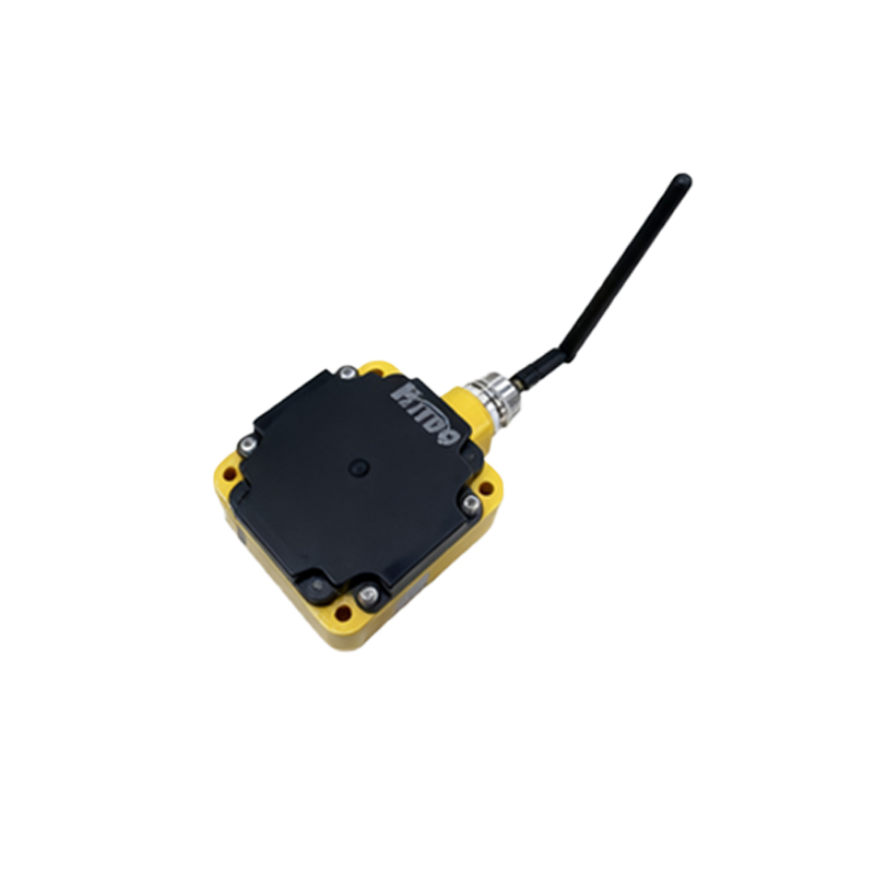
Critical Specifications and Selection Parameters
Choosing the correct sensor requires careful analysis of several parameters:
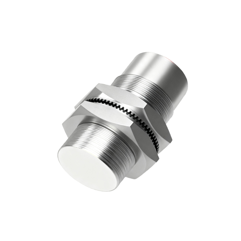
1. Sensing Distance: The nominal operating distance (Sn) is specified for a standard target (usually mild steel). For non-ferrous metals like aluminum or copper, the effective sensing distance is reduced and requires consultation of reduction factors.
2. Output Configuration: The choice between NPN (sinking) and PNP (sourcing) outputs must match the input circuit of the controller. NPN outputs switch the negative (0V) line, while PNP outputs switch the positive voltage line.
3. Output Function: Normally Open (NO) or Normally Closed (NC) defines the switch's resting state. An NO sensor conducts current when a target is detected, while an NC sensor interrupts current upon detection.
4. Supply Voltage: Common DC voltage ranges are 10-30 VDC or 10-65 VDC. Ensuring a stable, ripple-free power supply within this range is crucial for consistent operation.
5. Switching Frequency: This parameter, measured in Hertz (Hz), defines how quickly the sensor can detect objects passing by. High-speed applications, such as counting small parts on a conveyor, require a high switching frequency.
6. Housing Material: Typically constructed from nickel-plated brass, stainless steel, or specialized plastics like PBT, the material choice impacts chemical resistance, temperature tolerance, and resistance to physical damage.
7. Indicator LED: Most sensors feature an LED that indicates power status and output switching, invaluable for commissioning and troubleshooting.
Installation and Application Considerations
Proper installation is paramount for optimal performance. Designers must account for the "flush-mountable" or "non-flush-mountable" characteristic. Flush-mountable sensors can be installed flush with a metal mounting bracket without affecting their sensing range, whereas non-flush models require a clear frontal area. Lateral and axial mounting distances to adjacent sensors or metal surfaces must adhere to manufacturer guidelines to prevent mutual interference. These sensors are workhorses in countless applications: precise positioning control in CNC machines, part presence verification in assembly lines, end-of-travel detection in actuators, and high-speed counting in packaging machinery. Their immunity to ambient light, oil, coolant, and vibration makes them superior to optical or mechanical limit switches in harsh industrial settings.
Troubleshooting Common Issues
Even robust sensors can encounter problems. Frequent failure may stem from voltage spikes or excessive current load; using protective circuits or relays is recommended. Erratic switching can be caused by electrical noise from variable frequency drives (VFDs) or welding equipment; employing shielded cables and proper grounding is essential. If a sensor fails to detect a target, verify the target material and size, ensure it is within the specified sensing