In the realm of industrial automation and control systems, proximity sensors are indispensable components. They provide non-contact detection of objects, enabling precise, reliable, and wear-free operation in demanding environments. A fundamental understanding of their working principle, often best visualized through diagrams, is crucial for engineers and technicians involved in system design, integration, and maintenance. This article delves into the core operational concepts of common proximity sensor types, explaining the principles behind the diagrams.
The primary function of a proximity sensor is to detect the presence or absence of a target object within its sensing range without physical contact. This is achieved by emitting a field or beam and monitoring changes in its return signal or the field's properties. The working principle diagram typically illustrates the key internal components: the oscillator, the sensing coil or emitter, the signal conditioning circuit, and the output switching circuit.
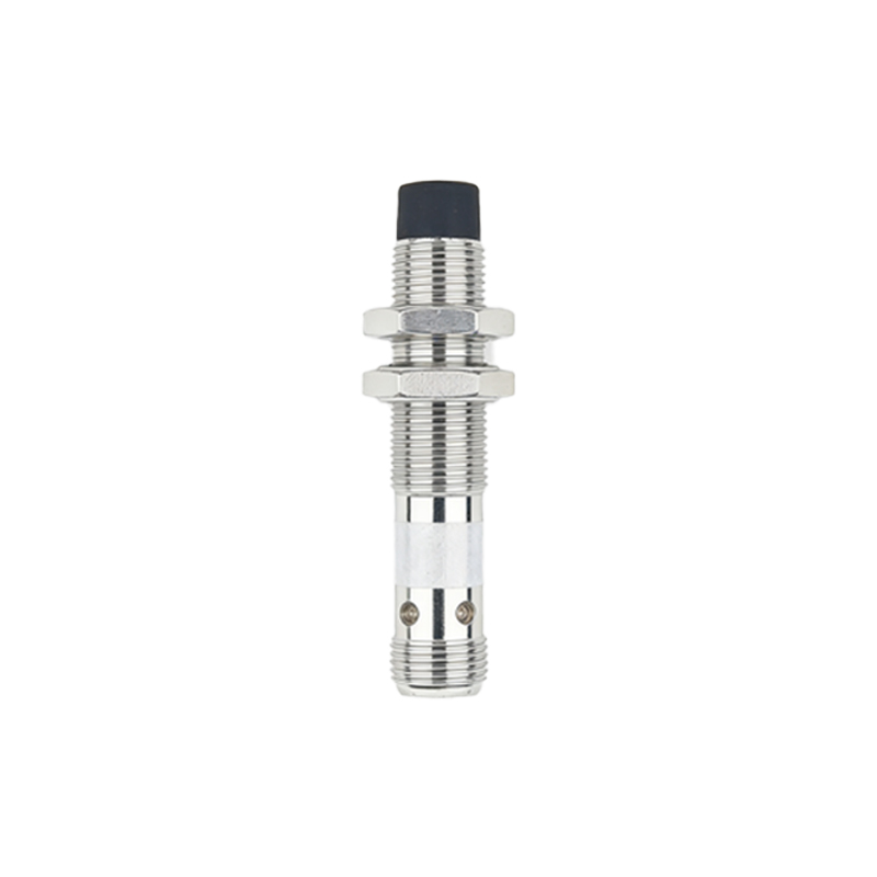
1. Inductive Proximity Sensors
The working principle diagram for an inductive proximity sensor centers on electromagnetic induction. The core component is an oscillator circuit that generates a high-frequency alternating magnetic field at the active face of the sensor, emanating from a coil wound around a ferrite core. When a metallic target (ferrous or non-ferrous) enters this oscillating field, eddy currents are induced on the surface of the target. These eddy currents draw energy from the oscillator, causing a reduction in the oscillation amplitude. This amplitude change is detected by a threshold circuit (trigger circuit). Once the amplitude drop exceeds a preset threshold, the sensor's solid-state output (typically NPN or PNP transistor) switches state, signaling the presence of the target. The diagram clearly shows the magnetic field lines, the target, the eddy current loops, and the signal path from oscillator to output.
2. Capacitive Proximity Sensors
A capacitive proximity sensor diagram explains operation based on capacitance change. The sensor face acts as one plate of a capacitor, with the target object (which can be metallic or non-metallic, liquid, or granular) acting as the other plate, and the air gap as the dielectric. The sensor contains an oscillator circuit where the capacitance of this formed capacitor is part of the resonant circuit. As a target approaches the active face, the capacitance increases. This alters the oscillator's characteristics, similar to the inductive type. A subsequent evaluation circuit monitors this change. When the capacitance change reaches a specific level, the output switches. The diagram typically highlights the electrostatic field lines between the sensor electrode and the target, illustrating how different materials affect the field.
3. Ultrasonic Proximity Sensors
The principle diagram for an ultrasonic sensor is based on sound wave propagation. It features a piezoelectric transducer that acts as both transmitter and receiver. The working cycle involves the transmitter emitting a burst of high-frequency ultrasonic sound waves. These waves travel through the air, hit a target object, and are reflected back as an echo. The receiver detects this echo. An internal timer circuit measures the time interval between the emission and the reception of the echo. Using the known speed of sound in air, the sensor's electronics calculate the distance to the target. An output is activated when the calculated distance falls within the preset sensing window. The diagram visually represents the sound wave pulses, their path to the target, and the reflected echo.
4. Photoelectric Proximity Sensors
Photoelectric sensors, while often used for longer ranges, also function as proximity devices in diffuse (reflective) mode. The principle diagram shows an integrated unit containing both a light emitter (usually an LED producing visible red, infrared, or laser light) and a photoelectric receiver (phototransistor or photodiode). In the diffuse mode, the emitted light strikes a target and is scattered. A portion of this scattered light reflects back to the receiver. The intensity of the received light is evaluated. When a target is present within the sensing range, the received light intensity exceeds a threshold, triggering the output switch. The diagram illustrates the light beam path and the diffuse reflection pattern.
Understanding these diagrams is vital for proper sensor selection. Key parameters derived from the principles include sensing distance, repeatability, hysteresis (the difference between the switch-on and switch-off points), and the influence of target material, size, and color. For instance, an inductive sensor diagram explains why only metals are detected, while a capacitive diagram shows sensitivity to material composition and density.
In conclusion, proximity sensor working principle diagrams are not merely illustrations; they are essential tools for comprehending the underlying physics of detection. From the electromagnetic fields in inductive sensors to the capacitive coupling, sound wave reflection, and light beam modulation in others, these diagrams empower engineers to deploy sensors effectively, troubleshoot issues accurately, and optimize automated systems for maximum reliability and efficiency. Mastery of these concepts ensures the correct sensor is chosen for the application, considering factors like target material, environmental conditions, and required response time.