Proximity sensors are indispensable components in modern industrial automation, providing non-contact detection of metallic or non-metallic objects. Proper wiring is critical to ensure reliable operation, safety, and longevity of these sensors in demanding environments. This guide outlines fundamental wiring principles, common configurations, and best practices for engineers and technicians.
Proximity sensors typically operate on DC or AC voltage, with DC versions being more prevalent in contemporary systems due to their compatibility with programmable logic controllers (PLCs). A standard three-wire DC sensor includes wires for power supply (brown), ground (blue), and output signal (black). The brown wire connects to the positive DC voltage terminal, usually 10-30 VDC, while the blue wire links to the common ground or negative terminal. The black output wire interfaces with the PLC input module or relay, completing the circuit when an object is detected. For two-wire AC sensors, wiring integrates directly into the AC power line; one wire connects to the live conductor, and the other to the load, simplifying installation but requiring careful attention to voltage ratings.
Shielding and cable management are essential to prevent electromagnetic interference (EMI), which can cause false triggering or signal loss. Use shielded cables grounded at one end, typically at the control panel, to minimize noise. Avoid routing sensor cables parallel to high-voltage power lines; cross them at right angles if necessary. For long cable runs exceeding recommended lengths—often 100 meters for analog sensors—consider using signal conditioners or repeaters to maintain signal integrity. Additionally, adhere to IP (Ingress Protection) ratings by selecting connectors and enclosures suitable for the environment, such as IP67 for dust and water resistance in harsh areas.
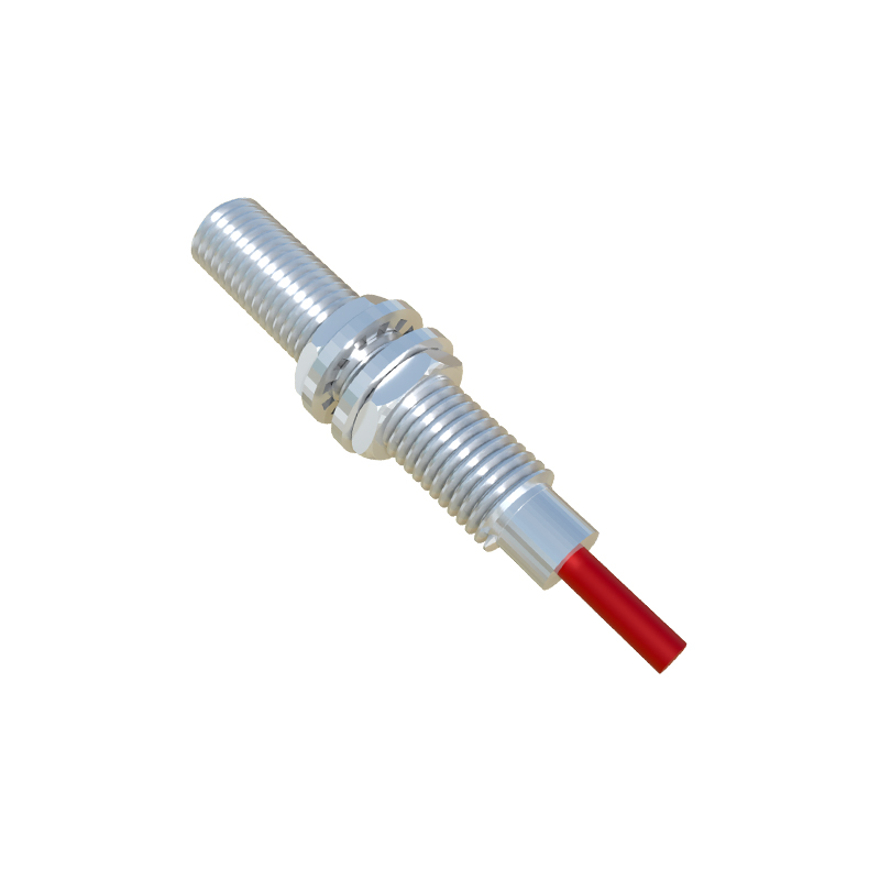
Wiring diagrams vary based on sensor type (NPN vs. PNP) and output configuration (normally open or normally closed). NPN sensors, common in Asian and European markets, sink current to ground when activated, with the output switching to low voltage. In contrast, PNP sensors, favored in North America, source current to the load, with the output switching to high voltage. Always verify the sensor’s datasheet to match wiring with the control system’s input requirements. For fail-safe applications, use normally closed circuits that trigger an alarm if the wire breaks, enhancing system safety.
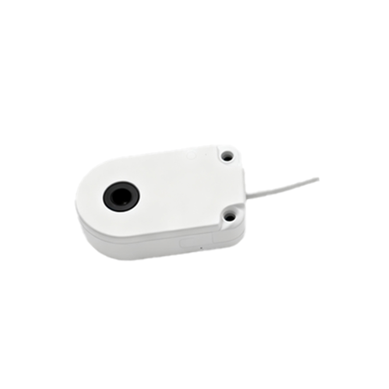
Testing and maintenance protocols ensure ongoing performance. After wiring, conduct a functional test by introducing a target object within the sensor’s sensing range, checking for a corresponding output signal via a multimeter or PLC indicator. Regularly inspect connections for corrosion, loose terminals, or physical damage, especially in vibrating or high-temperature settings. Implement preventive maintenance schedules, including cleaning lens surfaces on inductive or capacitive sensors to avoid false readings from debris.
In summary, meticulous wiring of proximity sensors underpins efficient automation. By following manufacturer guidelines, accounting for environmental factors, and aligning with regional standards, engineers can optimize detection accuracy and reduce downtime. As Industry 4.0 advances, integrating smart sensors with IoT platforms will further emphasize the need for robust wiring practices to support data-driven operations.