Infrared proximity sensors are widely used in various industrial and consumer applications due to their non-contact detection capability and reliability. This article provides a comprehensive guide to designing and implementing an infrared proximity sensor circuit, covering key components, circuit diagrams, and practical considerations.
The basic principle of an infrared proximity sensor involves emitting infrared light and detecting its reflection from nearby objects. A typical circuit consists of an infrared LED as the emitter and a photodiode or phototransistor as the receiver. The emitter section is driven by a modulated signal to reduce interference from ambient light, while the receiver section amplifies and processes the reflected signal.
A standard circuit design includes the following components: an oscillator circuit to generate a modulation signal (often using a 555 timer or microcontroller), a current-limiting resistor for the infrared LED, a photodiode with a reverse bias configuration, and an operational amplifier (op-amp) for signal conditioning. The op-amp is configured as a transimpedance amplifier to convert the photodiode's current output into a voltage signal. Additional filtering stages, such as band-pass filters, can be added to enhance signal-to-noise ratio.
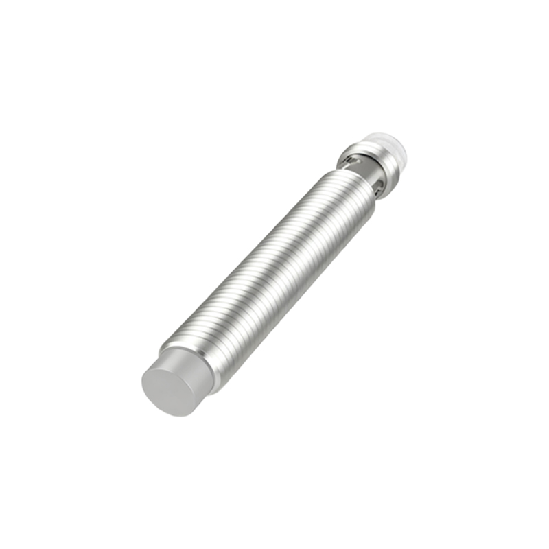
For practical implementation, start by assembling the emitter circuit. Connect the infrared LED in series with a resistor to limit current to a safe value (e.g., 20-30 mA). Use the oscillator to drive the LED at a frequency between 30-40 kHz, which is optimal for minimizing interference. In the receiver circuit, place the photodiode close to the LED but shielded to prevent direct coupling. Connect the photodiode to the inverting input of the op-amp, with a feedback resistor to set gain. A capacitor in parallel with the feedback resistor can help filter high-frequency noise.
Calibration is crucial for accurate detection. Adjust the gain of the op-amp based on the desired detection range, and fine-tune the oscillator frequency to match the receiver's filter characteristics. Testing should be conducted under varying lighting conditions to ensure robustness. For advanced applications, microcontrollers like Arduino or PIC can be integrated for digital signal processing, enabling features such as adjustable sensitivity and object distance estimation.
Common challenges include false triggers from ambient infrared sources (e.g., sunlight) and limited range in dark or reflective environments. To mitigate these, use optical filters to block unwanted wavelengths and implement software algorithms for signal validation. Always refer to datasheets for component specifications, and consider power consumption constraints in battery-operated devices.
In summary, designing an infrared proximity sensor circuit requires attention to modulation, amplification, and filtering. By following these guidelines, engineers can create reliable sensors for automation, robotics, safety systems, and more. Experiment with different layouts and components to optimize performance for specific use cases.