In industrial automation and control systems, proximity sensors are indispensable components for detecting the presence or absence of objects without physical contact. Among the various types, two-wire proximity sensors are widely favored for their simplicity and direct integration into control circuits. Unlike their three-wire or four-wire counterparts, two-wire sensors function as a switch in series with the load, simplifying wiring but requiring careful consideration of electrical characteristics. This guide provides a detailed, professional walkthrough on correctly wiring two-wire DC and AC proximity sensors, ensuring reliable operation and system longevity.
Understanding Two-Wire Proximity Sensor Fundamentals
A two-wire proximity sensor has only two connecting wires: one for power (line) and one for the load (load). It operates like a normally open (NO) or normally closed (NC) switch. In the DC version, polarity is crucial; one wire is typically connected to the positive DC supply, and the other to the load, which then connects to the negative supply (common). For AC sensors, the two wires are connected in series with the AC line and the load, and polarity is generally not a concern. A critical parameter is the leakage current (or residual current). Even when the sensor is in the "off" state (no target detected), a small current flows through the sensor. This current must be less than the holding current of the load (e.g., a PLC input or relay coil) to prevent false triggering. Conversely, the voltage drop across the sensor in the "on" state must be considered to ensure sufficient voltage reaches the load.
Wiring a Two-Wire DC Proximity Sensor
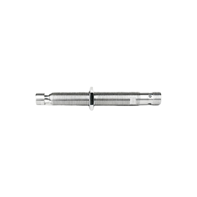
For a DC sensor (commonly 10-30V DC), follow these steps:
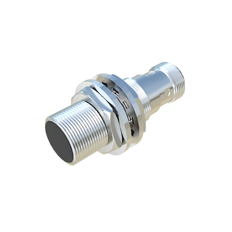
1. Identify Specifications: Check the sensor's datasheet for its nominal voltage (e.g., 24V DC), switching current limits, and leakage current (typically 0.1-1.8 mA).
2. Power Supply Connection: Connect one wire (often brown) to the positive terminal (+) of your DC power supply.
3. Load Connection: Connect the other wire (often blue) to one terminal of your load device (e.g., the positive input terminal of a PLC digital input module, or one side of a relay coil).
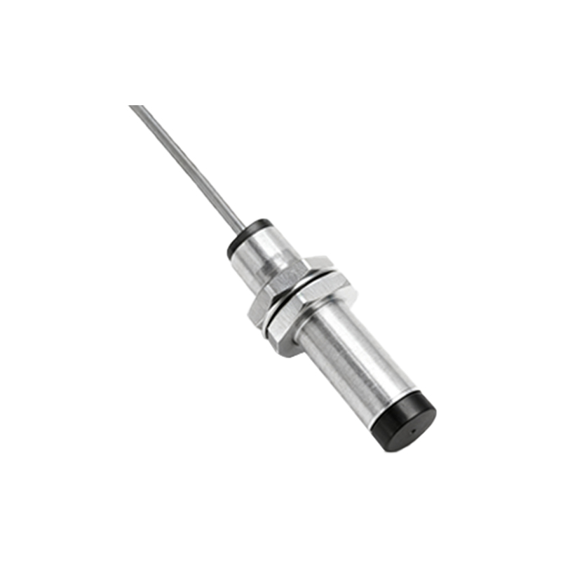
4. Complete the Circuit: Connect the other terminal of the load device back to the negative terminal (-) of the DC power supply.
5. Critical Check - Load Compatibility: Verify that the PLC input's or relay's minimum operating current is lower than the sensor's rated switching current, and its maximum off-state current (the current it can tolerate without turning on) is higher than the sensor's leakage current. If the leakage current is too high for a PLC input, a bleeder resistor (shunt resistor) wired in parallel with the load can be used to divert excess current.
Wiring a Two-Wire AC Proximity Sensor
For an AC sensor (commonly 90-250V AC), the process is similar but with AC power considerations:
1. Identify Specifications: Note the voltage range (e.g., 90-250V AC) and current ratings.
2. Circuit Integration: Connect one sensor wire (often brown) to the live (L) or phase conductor of the AC power source.
3. Series Connection: Connect the other sensor wire (often blue) to one terminal of the load (e.g., a contactor coil or an AC input module).
4. Neutral Completion: Connect the remaining terminal of the load to the neutral (N) conductor of the AC power source.
5. Considerations: AC sensors often have a higher residual current. Ensure the load's impedance is low enough to prevent this current from causing a voltage drop that could inadvertently energize the load. Using a load with a lower impedance or a dedicated bypass device may be necessary.
Best Practices and Troubleshooting
Always Refer to the Datasheet: Wiring colors and pinouts can vary by manufacturer. The datasheet is the ultimate authority.
Use Correct Wire Gauge: Select wires based on the sensor's current rating and installation distance.
Implement Proper Protection: Incorporate fuses or circuit breakers in the power line to protect against short circuits. For DC sensors, transient voltage suppressors are recommended in environments with inductive loads like solenoids or motors.
Ensure Proper Mounting: Maintain the specified sensing distance and avoid mounting metallic sensors too close to each other or to metal surfaces to prevent mutual interference.
Common Issues:
Load Doesn't Turn Off: This is frequently caused by excessive leakage current. Measure the