Inductive proximity sensors are fundamental components in industrial automation, renowned for their non-contact detection of metallic objects. At the heart of their operation lies a continuous high-frequency oscillation generated by an LC resonant circuit, typically involving a coil and a capacitor. This oscillation creates an alternating electromagnetic field at the active face of the sensor. When a conductive target enters this field, eddy currents are induced within the target. These eddy currents draw energy from the oscillator circuit, causing a measurable change in the oscillation amplitude or frequency. This change is detected by the sensor's evaluation circuit, which subsequently triggers a switching output signal. This state—where the oscillator is actively generating a stable electromagnetic field—is the normal, quiescent "oscillation" mode.
The term "cessation" or "damping" refers to the specific condition where the oscillation is sufficiently attenuated or stopped due to the presence of a target. This is the intended operational response. The sensor is designed so that when a target of the correct material, size, and distance (within the rated sensing distance) enters the field, the energy loss from eddy currents causes the oscillation amplitude to fall below a critical threshold. The evaluation circuit interprets this as a "target present" state and changes its output accordingly. For a normally open (NO) sensor, the output switches ON; for a normally closed (NC) sensor, it switches OFF. The point at which this occurs is precisely defined by the sensor's specifications.
However, operational issues can arise when oscillation or cessation occurs unexpectedly or unstably. Understanding these anomalies is crucial for troubleshooting.
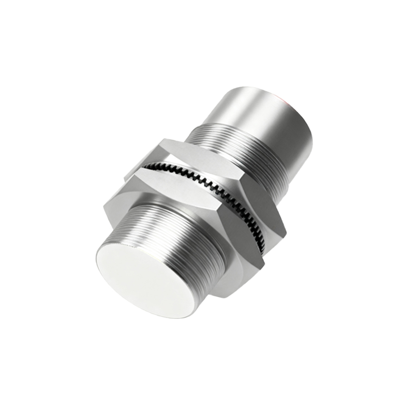
Unintended Cessation (False Triggering): This occurs when the sensor's oscillation stops or dampens without a valid target within its nominal sensing range. Common causes include:
1. Incorrect Target Material: Sensors are calibrated for specific metals (e.g., mild steel). Non-ferrous metals like aluminum or copper have different eddy current responses, requiring a reduction factor. Using an unsuitable material can cause erratic damping.
2. Environmental Interference: Strong external electromagnetic fields from large motors, transformers, or welding equipment can couple into the sensor's coil, distorting the oscillation and causing false triggers. Proper shielding and maintaining distance from such sources are essential.
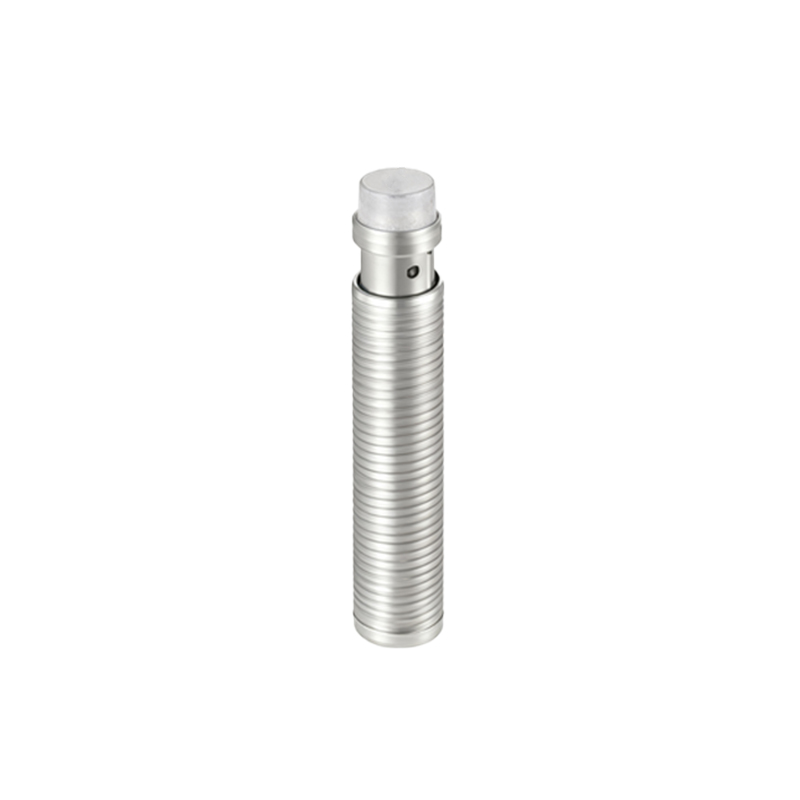
3. Metallic Debris or Background: Small metal chips, swarf, or even a nearby metal machine structure (the "background") can interact with the field. Ensuring a clean environment and adhering to the specified non-flush mounting distances for shielded sensors mitigates this.
4. Sensor Misalignment or Vibration: Physical movement can cause a target to momentarily enter and exit the sensing field, leading to a chattering output signal.
5. Electrical Noise on Supply Lines: Voltage spikes or noise on the DC power supply can disrupt the sensitive oscillator circuit. Using filtered power supplies and ensuring proper grounding are critical preventive measures.
Failure to Oscillate or Dampen: This is when the sensor remains in its quiescent state despite a valid target being present. Potential root causes are:
1. Power Supply Issues: Voltage outside the specified operating range (e.g., 10-30 VDC) can prevent the oscillator from starting or functioning correctly. Always verify supply voltage under load.
2. Incorrect Wiring or Load: Exceeding the maximum output current, causing a short circuit, or incorrect wiring (e.g., mixing up PNP and NPN types with the load) can damage the output stage or inhibit operation.
3. Target-Related Factors: The target may be outside the sensing range, too small, or made of an entirely non-conductive material (e.g., plastic, wood) which does not induce eddy currents.
4. Sensor Damage: Physical impact, especially to the sensing face, can damage the coil or ferrite core. Exposure to excessive temperatures, chemicals, or moisture can also degrade internal components, leading to permanent failure of the oscillator circuit.
5. Internal Component Failure: Over time, capacitors in the LC circuit can drift in value or fail, shifting the resonant frequency outside operational bounds.
Diagnostic and Best Practices:
A systematic approach is key. Begin by verifying the electrical installation: correct voltage, proper wiring, and an undamaged cable. Use an oscilloscope to monitor the oscillator's signal if possible; a clean, stable sine wave indicates healthy oscillation. For false triggering, methodically eliminate potential sources of interference and ensure the target and mounting conditions meet the sensor's datasheet requirements. Always consult the manufacturer's documentation for specific technical data, including sensing curves for different materials, temperature ratings, and immunity specifications.
In summary, the precise control between oscillation and cessation is what makes inductive sensors reliable. By comprehending the underlying electromagnetic principles and the common pitfalls