In the world of CNC engraving, precision and reliability are paramount. A critical, yet often overlooked, component ensuring this is the proximity switch sensor. These non-contact sensors act as the machine's tactile sense, providing essential positional feedback to the controller. For engineers, technicians, and operators, knowing exactly where to find these sensors is crucial for troubleshooting, maintenance, and optimizing machine performance. This guide details the common and critical locations of proximity switch sensors on a standard CNC engraving machine.
The primary function of a proximity sensor on an engraving machine is to detect the presence or absence of a metal target without physical contact, typically using inductive technology. They define machine limits and establish precise reference points (home positions) for each axis. Their placement is strategic and follows the machine's kinematic chain.
1. Axis Limit and Home Positions
This is the most fundamental location. You will find proximity sensors at the extreme ends of each linear axis travel: X, Y, and Z.
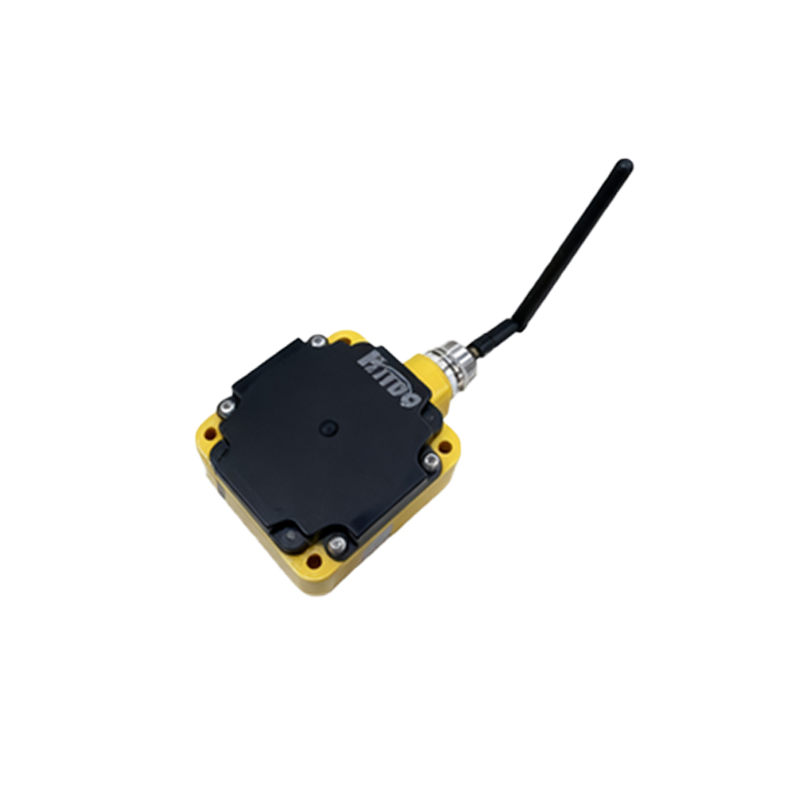
Negative Limit Sensors: Located at the "zero" or start-of-travel end of each axis rail or ball screw. They prevent the gantry or spindle from crashing into the mechanical frame.
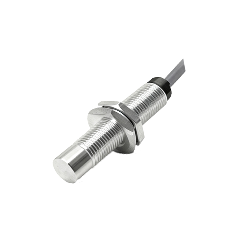
Positive Limit Sensors: Positioned at the opposite, far end of the travel. They define the maximum working envelope.
Home Sensor (or Reference Sensor): Often a separate sensor located near the negative limit. The machine "homes" by moving slowly towards this sensor until it triggers, establishing a repeatable datum point for all subsequent coordinates. Sometimes, the negative limit sensor doubles as the home sensor.
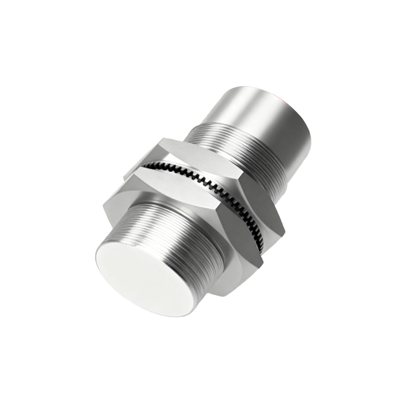
2. On the Moving Gantry and Spindle Assembly
Sensors are mounted on moving parts to detect fixed targets.
Z-Axis Assembly: The spindle carriage that moves up and down will have sensors (or the target flags for them) attached. Look for a small metal flag protruding from the carriage that passes through the fork of a sensor mounted on the stationary column. This defines the upper and lower limits of the Z-axis.
X and Y-Axis Gantry: For gantry-style machines, the entire bridge moves on the Y-axis. Sensors will be on the moving bridge ends, detecting targets on the machine base frame. The X-axis carriage (holding the Z-assembly) moves along the gantry beam, with its sensors detecting targets at either end of the beam.
3. Rotary Axis (4th Axis) Integration
On machines equipped with a rotary axis (A-axis) for cylindrical engraving, proximity sensors are vital.
Rotary Home Position: A sensor is positioned to detect a key or flag on the rotary chuck or tailstock. This ensures the workpiece rotation starts from a known angular position, critical for wraparound engraving operations.
4. Tool Changer Systems (if equipped)
Automatic Tool Changers (ATCs) rely heavily on proximity sensors for sequencing and safety.
Tool Magazine Position: Sensors confirm the carousel or arm is in the correct index position for tool pickup or drop-off.
Tool Presence Detection: In the spindle, a sensor verifies that a tool is properly seated and clamped before starting a job.
Arm Position: Sensors monitor the extension and retraction of the tool-changing arm.
5. Enclosure and Safety Doors
Modern CNC engravers often have safety interlocks.
Door Status Sensors: A proximity sensor detects if the safety door or guard is closed. The machine will not operate if this sensor is not triggered, protecting the operator.
6. Ancillary and Custom Fixturing
For advanced applications, sensors can be added to custom fixtures.
Part Presence Detection: A sensor can verify a workpiece is correctly loaded on a vacuum table or fixture before machining begins.
Fixture Alignment: Sensors ensure pallets or fixtures are precisely located.
Identification and Troubleshooting Tips:
When locating these sensors, look for small, cylindrical or rectangular devices (often black, blue, or metallic) with a sensing face, connected by a shielded cable to an I/O module. A metal "flag" or "dog" is usually positioned to pass within a few millimeters of this face. Common issues include misalignment, accumulation of metallic dust on the sensor face (causing false triggers), or mechanical damage to the flag. Always refer to the machine's specific electrical and mechanical diagrams for the definitive sensor map.
Understanding the topography of proximity switch sensors empowers you to maintain peak machine accuracy, diagnose faults efficiently, and ensure safe, uninterrupted production. Regular inspection of these locations should be a standard part of any preventive maintenance routine.