In the realm of industrial automation and machine control, proximity sensors are indispensable components for non-contact object detection. Among the various configurations, the 4-wire DC proximity sensor stands out for its unique functionality and widespread application. This article delves into the technical specifics, wiring methodology, operational principles, and key advantages of these sensors, providing a comprehensive guide for engineers and technicians.
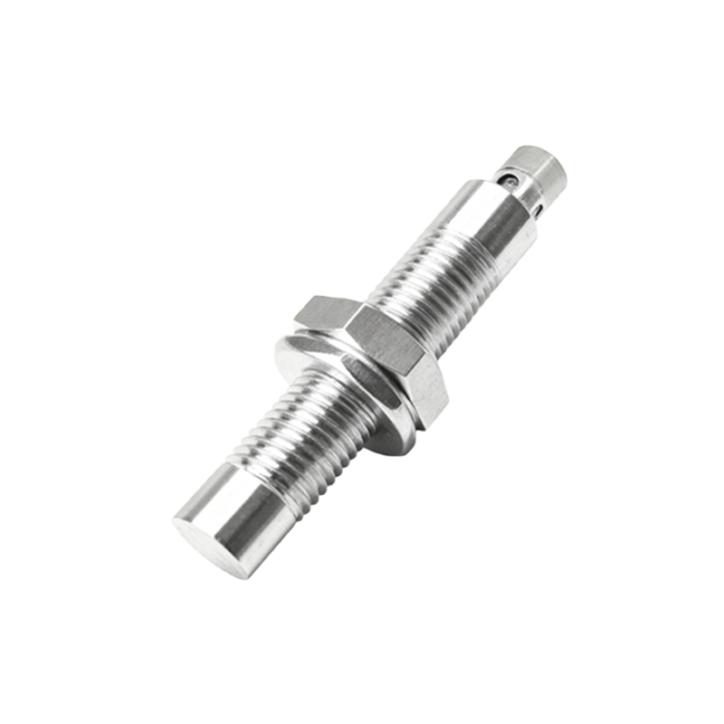
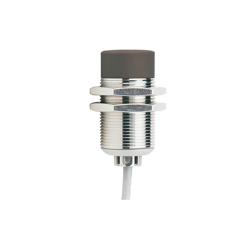
A 4-wire DC proximity sensor is an active electronic device designed to detect the presence or absence of a metallic or, in some cases, non-metallic target without physical contact. The "4-wire" designation refers to its electrical connection points, which typically consist of two wires for power supply and two wires for the output signal. This configuration is distinct from 2-wire or 3-wire sensors and offers a specific set of benefits. The core technology is often based on inductive, capacitive, or magnetic principles, with inductive types being most common for metal detection.
The standard wiring configuration for a 4-wire DC sensor is straightforward yet critical for proper operation. The four wires are usually color-coded according to international standards (though variations exist, and datasheets are paramount):
Brown Wire: Connected to the positive DC supply voltage (e.g., +10 to +30 VDC).
Blue Wire: Connected to the negative DC supply voltage or 0V (common).
Black Wire: This is the output signal wire. In a normally-open (NO) configuration, it switches the load to the positive supply when a target is detected.
White Wire: This is the second output signal wire. It typically provides the complementary function to the black wire. For instance, if black is NO, white is often normally-closed (NC). Alternatively, it can be a second independent NO output or used for different output types (e.g., NPN vs. PNP sourcing). The exact function must be verified with the manufacturer's documentation.

The primary operational advantage of a 4-wire design is the provision of dual, complementary, or independently controllable outputs. This allows a single sensor to perform two logical functions. For example, one output can trigger a "part present" signal to a PLC, while the complementary output can simultaneously de-energize a safety interlock or indicate a "part absent" state. This reduces component count, simplifies control logic, and saves panel space. Furthermore, the 4-wire design typically features a separate power supply circuit and output switching circuit. This separation minimizes leakage current and ensures a clean, stable output signal to the programmable logic controller (PLC) or relay, enhancing reliability and noise immunity compared to some 2-wire versions.
When integrating a 4-wire DC sensor, several key parameters must be considered. The sensing distance, or nominal range, is specified for a standard target and must not be exceeded. Output type is crucial: many 4-wire sensors offer a choice between solid-state transistor outputs (like NPN or PNP) or relay contacts. The black and white wires may configure these differently. Load compatibility—ensuring the sensor's output can handle the current and voltage of the connected load (e.g., PLC input, relay coil)—is non-negotiable. Always consult the sensor's datasheet for absolute ratings, wiring diagrams, and temperature specifications.
The applications for 4-wire DC proximity sensors are vast across manufacturing and processing industries. They are extensively used in:
Material Handling: Detecting pallet positions on conveyors, with one output for "in position" and another for "clear to advance."
Packaging Machinery: Verifying the presence of a product and simultaneously confirming that a guard door is safely closed using complementary NO/NC signals.
Robotic Workcells: Providing end-of-arm tooling status (open/closed) or part pick/place verification.
Assembly Automation: Performing pass/fail checks where two distinct control signals are required based on a single detection event.
Troubleshooting these sensors generally involves checking the power supply voltage at the brown and blue wires with a multimeter. Next, monitor the output wires (black/white) for a voltage change when a target is presented within the sensing range. The LED indicator on the sensor housing is a vital diagnostic tool, showing power status and output activation. Common issues include incorrect wiring, supply voltage mismatch, excessive load current, or sensing range problems due to an incorrect target material.
In summary, the 4-wire DC proximity sensor is a versatile and robust solution for advanced control scenarios requiring multiple output states from a single detection point. Its design offers enhanced electrical isolation, reliable performance, and logical flexibility. For engineers designing or maintaining automated systems, understanding the wiring, function,