In the realm of industrial automation and electronic control systems, proximity Hall-effect sensors stand as critical components for non-contact detection of magnetic objects. Their operation hinges on the Hall effect, a fundamental physical principle discovered by Edwin Hall in 1879. This article delves into the schematic diagram of a typical proximity Hall-effect sensor, elucidating its core circuitry and operational logic to provide engineers and technicians with a clear, practical understanding.
At the heart of the schematic lies the Hall element itself. It is typically represented by a small square or diamond symbol with four terminals: a supply voltage (VCC), ground (GND), and two output terminals. When a magnetic field of sufficient strength and correct polarity is applied perpendicular to the Hall element, a small differential voltage, known as the Hall voltage (VH), appears across its output terminals. This voltage is proportional to the product of the control current (through VCC/GND) and the magnetic flux density.
However, the raw Hall voltage is minuscule, often in the millivolt range, and susceptible to noise and temperature variations. Therefore, the schematic integrates signal conditioning circuitry directly. This almost always includes a high-gain differential amplifier. The amplifier's primary function is to boost the weak Hall voltage to a robust, usable level. Modern integrated Hall sensor ICs incorporate this amplifier on the same silicon die as the Hall plate. Following amplification, the signal is fed into a Schmitt trigger circuit. The Schmitt trigger provides hysteresis, which is crucial for noise immunity. It ensures a clean, sharp digital output transition (from logic high to low, or vice versa) when the magnetic field crosses a predefined threshold, preventing erratic toggling if the sensed magnetic field is at the borderline.
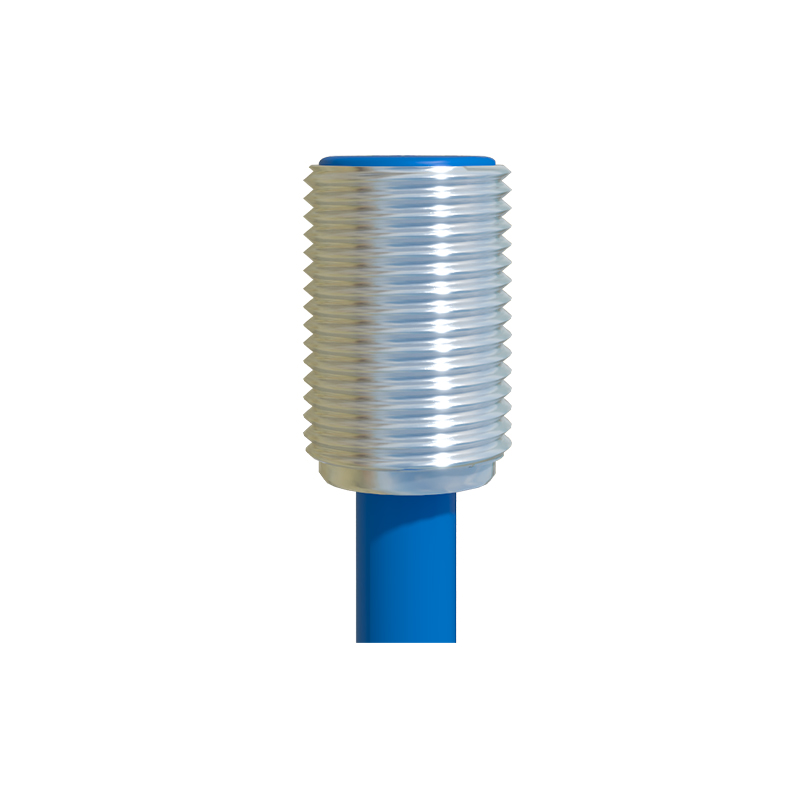
The output stage of the schematic defines the sensor's interface with the wider control system. Two primary output configurations are prevalent: open-collector (or open-drain) and push-pull. In an open-collector schematic, the output transistor's collector is floating internally and requires an external pull-up resistor to the positive supply rail. When the sensor is activated by a magnetic field, this transistor switches on, pulling the output line low to ground (GND). In the absence of the field, the transistor is off, and the pull-up resistor brings the output line high. This configuration offers flexibility in interfacing with different logic voltage levels. The push-pull output stage, conversely, uses complementary transistors to actively drive the output line both high and low without needing an external resistor, providing a stronger output signal.
A complete schematic also includes essential passive components for stability and protection. Decoupling capacitors, usually a 100nF ceramic capacitor placed close to the VCC and GND pins, are mandatory to filter high-frequency noise from the power supply. For applications in electrically noisy environments, such as near motors or solenoids, additional filtering at the output or the inclusion of a snubber circuit might be depicted. Furthermore, many sensor ICs include reverse polarity protection diodes in their internal schematic, safeguarding the device from accidental miswiring of the power supply.
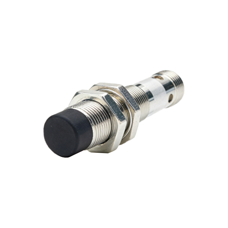
Analyzing the schematic for a specific application involves understanding its switching behavior. Datasheets specify whether the sensor is "unipolar" (responsive to a single magnetic south or north pole), "bipolar" (requires alternating poles to switch), or "omnipolar" (responds to either pole). This characteristic is determined by the internal circuitry's design and bias points. The schematic's legend or accompanying notes will also indicate critical parameters like operating voltage range (e.g., 3.5V to 24V DC), output sink/source current capability, and the magnetic switch point (Bop/BRP).
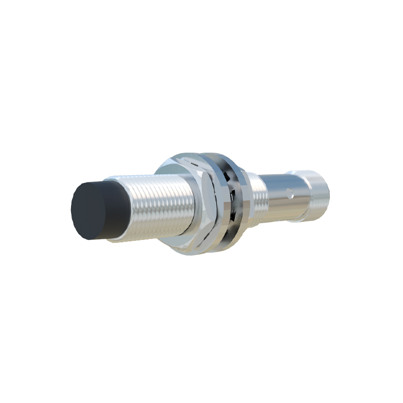
In practical design, the schematic serves as the blueprint for PCB layout. Keeping the loop areas for the power and signal traces small is paramount to minimize electromagnetic interference. The sensor must be positioned correctly relative to the target magnet, considering the sensitive axis of the Hall element, which is typically perpendicular to the face of the IC package.
In conclusion, the schematic diagram of a proximity Hall-effect sensor is more than just a collection of symbols; it is a detailed map of its functionality. From the generation of the Hall voltage to the conditioned digital output, each stage plays a vital role in creating a reliable, solid-state switching device. Mastery of this schematic empowers engineers to effectively select, integrate, and troubleshoot these indispensable sensors in diverse applications ranging from position sensing in machinery to speed detection in automotive systems.