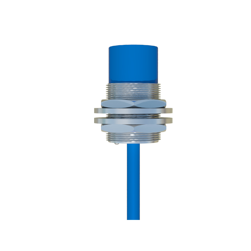
As a seasoned electrical engineer with years of hands-on experience in industrial automation, I often encounter issues with proximity switch sensors, particularly when the red indicator light illuminates unexpectedly. This red light typically signals a fault or abnormal condition that requires immediate attention to prevent downtime or equipment damage. Understanding how to diagnose and repair this problem is crucial for maintaining efficient operations in manufacturing, packaging, and machinery systems.
First, it's essential to recognize what the red light indicates. Proximity switches, including inductive, capacitive, and ultrasonic types, use LED indicators to communicate status. A steady or flashing red light usually points to errors such as wiring faults, power supply issues, sensor misalignment, or internal component failure. Before diving into repairs, always prioritize safety: disconnect power, lock out/tag out equipment, and wear appropriate personal protective equipment (PPE) to avoid electrical hazards.
Start by checking the power supply. Ensure the voltage matches the sensor's specifications (commonly 10-30V DC or 20-250V AC). Use a multimeter to measure voltage at the sensor terminals. If the reading is outside the acceptable range, inspect the power source, cables, and connectors for damage or loose connections. A low or unstable voltage can trigger the red light. Replace any frayed wires or corroded terminals, and verify that the grounding is secure to eliminate electrical noise interference.
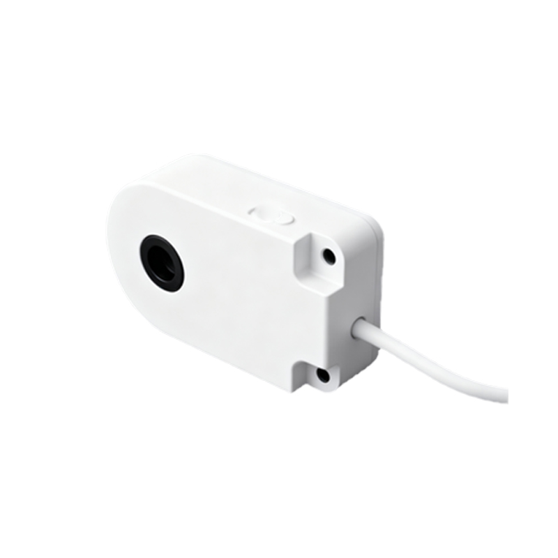
Next, examine the wiring configuration. Proximity switches typically have three wires: brown (positive), blue (negative), and black (output). Incorrect wiring, such as reversed polarity or short circuits, can cause the red light to activate. Refer to the manufacturer's datasheet for correct pinouts. Test continuity and insulation resistance with a multimeter to identify open circuits or shorts. If the wiring is correct, move on to the load connection—overloading the output with excessive current may trip the sensor's protection circuit, leading to a red indicator.
Sensor alignment and positioning are critical factors. For inductive proximity switches, ensure the target object is within the specified sensing range and made of appropriate material (e.g., metal for inductive types). Misalignment or debris accumulation on the sensor face can reduce sensitivity, triggering fault indicators. Clean the sensor surface with a soft cloth and realign it according to installation guidelines. For capacitive sensors, environmental changes like humidity or contamination might affect performance; adjust sensitivity settings if available.
Environmental conditions can also play a role. Extreme temperatures, moisture, vibration, or electromagnetic interference (EMI) from nearby motors or cables may cause false red lights. Check the sensor's IP rating and operating temperature range. If the environment is harsh, consider relocating the sensor or using shielded cables and protective enclosures. Additionally, inspect for physical damage such as cracks or dents that could compromise internal electronics.
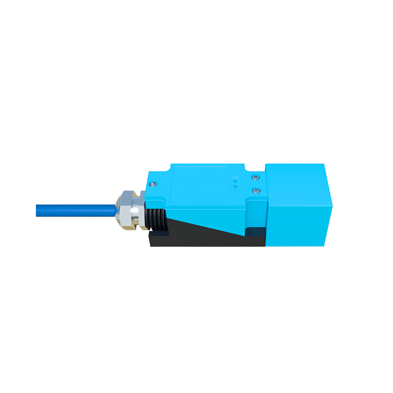
If basic checks don't resolve the issue, the problem may lie within the sensor's internal circuitry. Over time, components like oscillators, amplifiers, or output transistors can degrade. Some advanced proximity switches feature diagnostic modes accessible via push buttons or programming tools. Consult the user manual to enter diagnostic mode and interpret error codes. In cases of internal failure, replacement is often more cost-effective than repair, especially for sealed units. Before replacing, test the sensor with a known working unit to confirm the fault.
Preventive maintenance is key to avoiding recurring red light issues. Regularly inspect sensors for wear, clean them, and verify electrical connections. Keep a log of failures to identify patterns, such as frequent issues in high-vibration areas. Train personnel on proper installation and troubleshooting techniques to minimize errors.
In summary, fixing a red light on a proximity switch sensor involves systematic troubleshooting: verify power and wiring, check alignment and environment, and consider internal faults. By following these steps, you can quickly restore functionality and ensure reliable sensor performance in industrial applications. Always refer to manufacturer documentation for model-specific guidance, and when in doubt, consult with technical support for specialized assistance.