Inductive proximity sensors are vital components in industrial automation, detecting metallic objects without physical contact. Proper testing ensures their reliability, reduces downtime, and maintains system integrity. This guide outlines practical methods for testing inductive proximity sensors, covering tools, procedures, and common pitfalls.
First, understand the operating principle. Inductive sensors generate an electromagnetic field. When a metal target enters this field, eddy currents are induced, causing a change in oscillation amplitude or frequency. This triggers the sensor's output switch (typically NPN or PNP). Testing verifies that this response occurs within specified parameters.
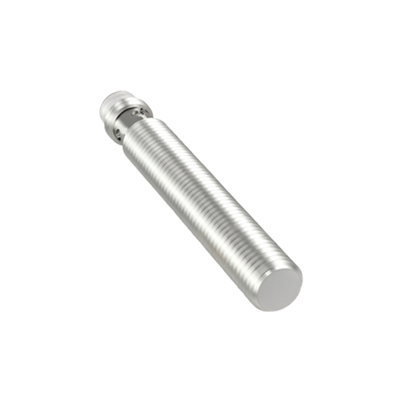
Essential tools include a multimeter, oscilloscope (optional for advanced diagnostics), a metal target (e.g., steel plate of correct size), and a power supply matching the sensor's voltage (commonly 10-30V DC). Always refer to the datasheet for specifications like sensing distance, hysteresis, and response time.
Basic Testing Procedure:
1. Power Connection: Connect the sensor to its rated voltage. Ensure correct polarity—brown wire to positive, blue wire to negative for DC sensors. The black wire is usually the output.
2. Output Verification: Use a multimeter set to voltage mode. Place the metal target within the nominal sensing distance. For a normally open (NO) sensor, the output should switch from low to high voltage (close to supply voltage when active). A normally closed (NC) sensor behaves oppositely.
3. Sensing Distance Check: Gradually move the target toward the sensor. Note the point where the output switches—this is the actual sensing distance. Compare it to the datasheet value. Factors like target material (steel, aluminum, copper) affect distance; ferrous metals yield longer ranges.
4. Hysteresis Evaluation: After activation, slowly retract the target. The switch-off point will differ from the switch-on point due to hysteresis. This prevents chatter. Measure the difference; typical hysteresis is 3-10% of the sensing distance.
Advanced diagnostics involve an oscilloscope to monitor output response time and waveform stability. Noise or jitter may indicate EMI issues or power supply problems. Additionally, check for false triggers by testing with non-metallic objects nearby.
Common issues include reduced sensing range (often from sensor coating buildup or misalignment), erratic output (due to wiring faults or incompatible targets), and no output (check power, wiring, or sensor damage). Environmental factors like temperature extremes, humidity, or strong magnetic fields can also impact performance. Regular maintenance, such as cleaning the sensor face and verifying mounting stability, extends lifespan.
In summary, systematic testing of inductive proximity sensors ensures accurate detection and prevents operational failures. Always follow manufacturer guidelines and integrate testing into routine maintenance schedules for optimal automation system performance.