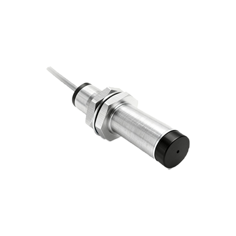
In the realm of industrial automation and machinery maintenance, proximity sensors play a critical role in detecting the presence or absence of objects without physical contact. A common query among engineers and technicians is whether a non-original code on a proximity sensor necessarily means the component has been replaced. This article delves into the technical nuances behind sensor coding, replacement indicators, and best practices for verification.
Proximity sensors, including inductive, capacitive, and magnetic types, often feature identification codes—such as part numbers, serial numbers, or batch codes—etched or printed on their housing. These codes serve multiple purposes: they authenticate the manufacturer, specify technical parameters (e.g., sensing range, voltage rating), and aid in traceability for quality control. Original equipment manufacturer (OEM) codes align with factory records and are typically consistent across production runs. When a sensor displays a code that deviates from the OEM standard, it can raise red flags about its provenance.
However, a non-original code does not automatically confirm a replacement. Several scenarios can explain code discrepancies without implying substitution. First, manufacturers may update coding systems due to rebranding, mergers, or production line changes, leading to variations in otherwise genuine parts. For instance, a sensor produced by Company X might bear a new alphanumeric sequence after a corporate acquisition, even if its internal components remain identical. Second, suppliers sometimes apply secondary labels for inventory management, which can obscure or supplement the original code. In such cases, the sensor might be authentic but appear altered due to logistical handling. Third, regional distribution practices can result in different coding formats for the same model, especially in global supply chains. A sensor destined for Europe might have a distinct code from its North American counterpart, though both are OEM-sourced.
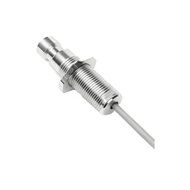
To accurately determine if a replacement has occurred, engineers should conduct a multi-faceted assessment beyond code inspection. Start by comparing the sensor's physical attributes—such as dimensions, connector type, and material finish—with OEM specifications. Even minor deviations in housing design or mounting threads can signal a non-genuine part. Next, perform functional testing using calibrated equipment to verify operational parameters like switching frequency, hysteresis, and temperature tolerance. A replaced sensor, particularly a counterfeit or lower-grade alternative, may exhibit performance gaps under load or in harsh environments. Additionally, review maintenance logs and procurement records; if a sensor was documented as replaced during a prior repair, the code mismatch likely confirms the swap.
In cases where replacement is suspected, consider the implications for system integrity. Non-OEM sensors might not meet the original durability or safety standards, potentially leading to false triggers, premature failure, or compatibility issues with controllers. For example, an inductive sensor with a mismatched code could have a different shielding material, affecting its detection stability near metal surfaces. Always prioritize sensors that comply with industry certifications (e.g., IEC 60947-5-2) to ensure reliability.
Ultimately, while a non-original code can be a clue, it should not be the sole criterion for judging sensor replacement. Engineers must integrate code analysis with technical verification and historical data. In dynamic industrial settings, proactive measures—such as standardizing part sourcing, using RFID tagging for traceability, and training staff on authentication techniques—can mitigate uncertainties. By adopting a holistic approach, teams maintain operational efficiency and safeguard machinery from suboptimal components.