Proximity sensors are indispensable components in modern industrial automation, providing non-contact detection of metallic and, in some cases, non-metallic objects. Their reliability, long service life, and high switching frequency make them superior to mechanical limit switches in countless applications. However, their performance is heavily dependent on correct installation. Improper placement can lead to false triggers, missed detections, premature failure, and costly downtime. This guide outlines critical considerations for determining the optimal installation location for inductive, capacitive, ultrasonic, and photoelectric proximity sensors.
The primary rule is to ensure the target object enters the sensor's effective sensing range or "switching zone" reliably and consistently. This zone is not a perfect sphere or cylinder; it is defined by the sensor's sensing distance (Sn), as specified in its datasheet. For inductive sensors detecting metals, the standard target is a square of mild steel (Fe360) with a thickness equal to the sensor's diameter or the sensing distance, whichever is greater. The target must approach the active sensing face perpendicularly. Mounting the sensor at an angle or expecting detection from the side will drastically reduce the effective sensing distance and reliability.
Environmental factors are paramount in selecting an installation site. For inductive sensors, the presence of other metals near the sensing face can cause interference. Maintain a minimum clearance between the sensor's face and any surrounding metal structure (like a machine guard or bracket). This "non-flush" mounting distance is typically one to two times the sensor's diameter. Flush-mountable sensors are designed to be embedded in metal without this clearance, but their sensing range is shorter. Always account for vibration and potential physical impact. Use sturdy brackets and consider sensors with robust housings (e.g., metal) in high-vibration areas. For photoelectric sensors, avoid locations with heavy ambient light (direct sunlight, welding arcs) or airborne contaminants like dust, steam, or oil mist that can coat the lens or scatter the light beam. In such environments, choosing a sensor with a specific housing rating (e.g., IP67, IP69K) and, for photoelectrics, a polarized lens or modulated LED light source is essential.
The nature of the target object itself dictates sensor choice and placement. For small targets, you may need to reduce the sensor's sensing distance (many models have potentiometers for this) or select a sensor with a narrower, more focused beam. For irregularly shaped or non-ferrous metal targets (aluminum, copper), inductive sensors will have a reduced range; consult the correction factors in the datasheet. Capacitive sensors for non-metallic materials (plastic, wood, liquid) must be positioned where the target material's dielectric constant will cause a sufficient change in the sensor's internal capacitance. They are highly sensitive to moisture and material composition changes.
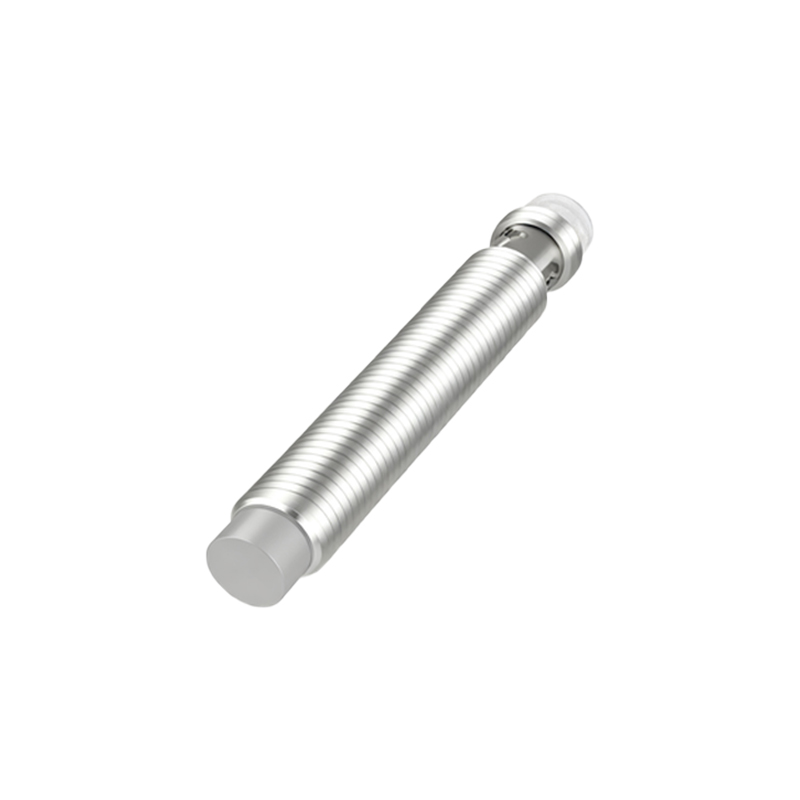
Consider the application's kinematics. Is the target moving linearly, on a rotating disk, or on a conveyor? For linear motion, position the sensor so the target passes directly in front of the sensing face. For rotary applications, like detecting teeth on a gear or flags on a shaft, ensure the gap between targets is sufficient for the sensor to reset. The sensor's response time and output switching frequency must be faster than the speed of the target. For example, a sensor with a 1ms response time can reliably detect objects passing at intervals greater than 1ms.
Electrical and wiring considerations also influence location. Ensure the installation point allows for proper cable routing to avoid sharp bends, tension, or exposure to moving parts. Use cable glands or connectors suitable for the environment. Keep sensor cables away from high-voltage power lines, motor drives, or welding equipment to prevent electromagnetic interference (EMI), which can cause erratic behavior. In high-EMI environments, use shielded cables and ground the shield properly at the controller end only.
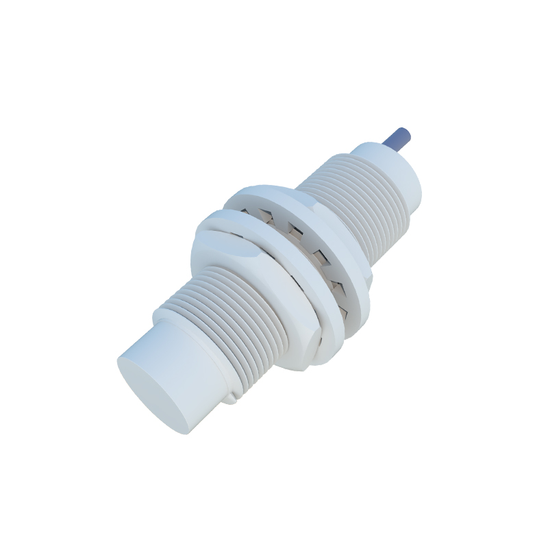
Finally, always prioritize accessibility for maintenance, adjustment, and replacement. A perfectly positioned sensor is of little use if it requires a two-hour machine teardown to service. Leave adequate space for tool access and cable connection.
In summary, the optimal installation point is where the sensor has a clear, reliable path to its intended target, is protected from environmental hazards and physical damage, is free from electrical and metallic interference, and remains accessible. Always reference the manufacturer's installation manual and datasheet for specific mounting dimensions, sensing curves, and environmental limits. Proper planning during the design and installation phase maximizes sensor lifespan and ensures seamless, trouble-free operation in your automation system.