In the intricate ecosystem of modern vehicle electronics, the Vehicle Speed Sensor (VSS), often implemented as a proximity switch, plays a pivotal role. Its data is critical for functions ranging from speedometer operation and cruise control to transmission shifting and anti-lock braking systems (ABS). For technicians, engineers, and automotive enthusiasts, a common and crucial question arises: Where is the vehicle speed sensor proximity switch located? The answer is not universal, as placement varies significantly by drivetrain configuration, manufacturer, and model year. This guide provides a detailed, professional overview of common and specific locations.
Fundamental Principles and Common Locations
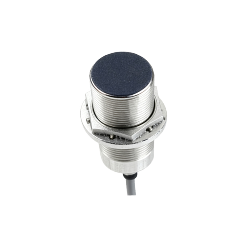
A vehicle speed sensor proximity switch typically operates on the Hall-effect or variable reluctance principle, detecting the rotation of a toothed reluctor wheel or gear. Its location is invariably tied to a rotating component whose speed directly correlates with road speed. The primary locations are:
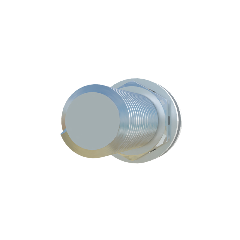
1. Transmission or Transaxle Output Shaft: This is arguably the most common location. Mounted on the transmission or transaxle case, the sensor monitors the rotation of the output shaft, which turns at a speed directly proportional to the driveshaft and, consequently, the wheels. It provides a precise signal for the vehicle's road speed, independent of engine RPM or gear selection. You'll often find it on the side or rear extension housing of the transmission. It may be secured by one or two bolts and have a simple electrical connector.
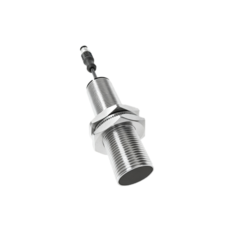
2. Transfer Case (4WD/AWD Vehicles): In four-wheel-drive and all-wheel-drive vehicles, the VSS is frequently located on the transfer case. This placement allows the engine control module (ECM) or transmission control module (TCM) to monitor the speed of the output shafts going to the front and/or rear axles, which is vital for advanced traction and stability control systems.
3. Wheel Hub / ABS Ring Integration: Modern vehicles often integrate wheel speed sensors, which are also proximity switches, into the ABS. While each wheel sensor provides individual data for braking control, the signal from a non-driven wheel (or a composite signal) is frequently used as the primary vehicle speed signal. In such architectures, there might not be a dedicated VSS on the transmission; the ABS control module calculates and broadcasts the vehicle speed data over the Controller Area Network (CAN bus).
4. Differential: On some rear-wheel-drive vehicles, particularly older models, the speed sensor may be mounted on the differential housing, reading the rotation of the ring gear or a dedicated tone ring on the differential carrier.
Vehicle-Specific Examples and Identification
Front-Wheel-Drive Cars (Transaxle): Look on the end of the transaxle, opposite the engine, often near the drive axle shafts. It is usually cylindrical, extending into the casing.
Rear-Wheel-Drive Cars & Trucks (Transmission): Check the rear extension housing of the transmission, where the driveshaft connects. It often points towards the output shaft's yoke or a dedicated tone ring.
Domestic Trucks & SUVs: Common on the transfer case (for 4x4) or the rear differential. Always trace the wiring harness from the rear axle or transfer case forward.
European Vehicles (e.g., BMW, Mercedes-Benz): These manufacturers have widely used ABS wheel speed sensors as the primary source for vehicle speed data for decades. The physical VSS on the transmission may be absent, replaced by a transmission output speed sensor used solely for internal transmission control.
Diagnostic and Procedural Notes
Locating the sensor is only the first step. Before replacement:
Consult Service Information: Always refer to the manufacturer's service manual or a reliable repair database for the exact location, part number, and removal procedure. A diagram is invaluable.
Electrical Inspection: Often, the fault lies in the wiring harness—chafed wires, corroded connectors, or poor grounds—rather than the sensor itself. Perform a thorough visual inspection and measure sensor resistance and output signal (AC voltage for VR sensors, digital square wave for Hall-effect) as specified.
Clearance is Critical: Proximity switches have a precise air gap (e.g., 0.5mm to 1.5mm) between the sensor tip and the reluctor ring. This gap is sometimes set by a shim or is non-adjustable. Incorrect gap will cause signal failure.
Magnetic Tip Contamination: The sensor tip can attract metallic debris from gear wear, which must be cleaned off for proper operation.
In summary, the vehicle speed sensor proximity switch is strategically located at a point of rotational measurement that best represents true road speed. While the transmission