Proximity sensors are indispensable components in modern industrial automation, playing a critical role in object detection, position sensing, and process control without physical contact. Understanding their wiring configurations is paramount for ensuring system reliability, safety, and optimal performance. This comprehensive guide provides a detailed collection of proximity sensor wiring diagrams, catering to the needs of electrical engineers, technicians, and automation specialists. We will explore various sensor types, standard connection methods, and practical implementation tips, all presented through clear, annotated diagrams.
The foundation of any proximity sensor installation lies in its electrical connection. Proximity sensors are broadly categorized by their output type: 2-wire, 3-wire, and 4-wire configurations. Each type has distinct wiring requirements and implications for circuit design.
1. 2-Wire Proximity Sensor Wiring:
The 2-wire sensor is the simplest type, acting like a switch in series with the load. It has only two terminals: one for connecting to the power supply (L+) and the other to the load. The sensor itself consumes a small leakage current even in the "off" state. A typical wiring diagram shows the brown wire (or L+) connected to the positive DC supply or phase of AC supply. The blue wire (or load wire) is connected to one terminal of the load (e.g., a PLC input, relay coil). The other terminal of the load is then connected to the power supply negative (DC) or neutral (AC). This configuration is cost-effective but sensitive to residual current and voltage drop across the sensor.

2. 3-Wire Proximity Sensor Wiring:
This is the most common configuration in industrial settings, offering separate paths for power supply and output signal, which enhances performance. Three-wire sensors come in two output polarities: NPN (sinking) and PNP (sourcing).
PNP (Sourcing) Wiring Diagram: The brown wire connects to the positive DC supply (+V). The blue wire connects to the DC common or negative (0V). The black wire is the output signal line. When the sensor detects a target, it sources current, meaning the output (black wire) switches to the supply voltage (+V). This signal is then connected to the PLC input or other control device.
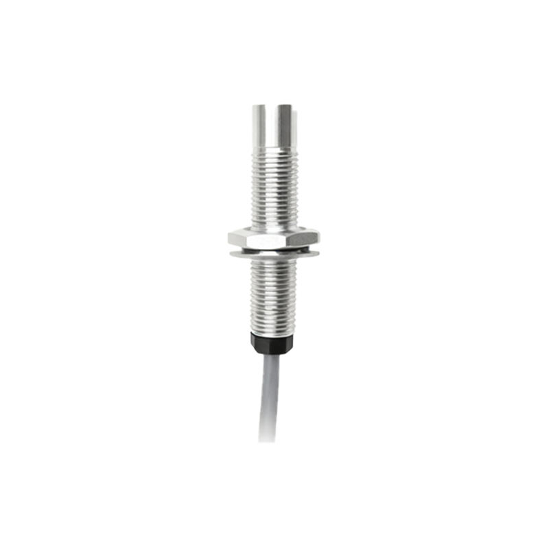
NPN (Sinking) Wiring Diagram: The brown wire connects to +V, and the blue wire to 0V. The black wire is again the output. For an NPN sensor, when activated, it sinks current to ground (0V). The load (PLC input) must be connected between the +V supply and the sensor's black output wire. Understanding the difference between PNP and NPN is crucial for compatibility with programmable logic controllers (PLCs).
3. 4-Wire Proximity Sensor Wiring:
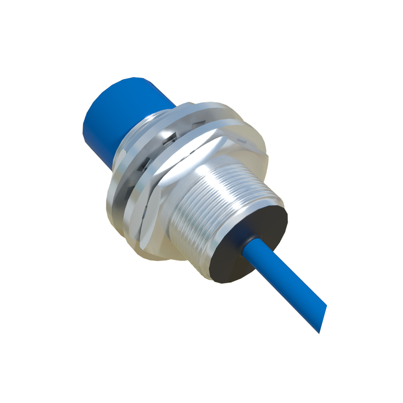
These sensors provide two complementary outputs, typically one NPN and one PNP, or sometimes two independent outputs (e.g., NO and NC). A standard 4-wire diagram shows connections for brown (+V), blue (0V), a black wire (often Output 1), and a white wire (often Output 2). This design offers great flexibility, allowing the same sensor to interface with different types of control logic within a single unit. The wiring diagram clearly illustrates how to connect each output to separate control points.
Wiring Considerations for Different Sensor Technologies:
The core technology—inductive, capacitive, or ultrasonic—also influences wiring practices, though the terminal configurations remain similar.
Inductive Proximity Sensors: Used for detecting metallic objects. Diagrams often include symbols for the sensing face and specify shield or unshielded types, which can affect mounting and wiring proximity to metal.
Capacitive Proximity Sensors: Can detect non-metallic materials. Wiring diagrams are identical to inductive types, but installation notes emphasize avoiding interference from conductive dust or contaminants on the face.
Analog Output Sensors: Instead of a simple on/off switch, these sensors provide a voltage or current signal proportional to distance. Their wiring diagrams include an additional wire for the analog signal (e.g., a yellow wire for a 4-20mA output) and require connection to an analog input module on a PLC.
Essential Implementation Guidelines:
1. Always Refer to the Datasheet: The manufacturer's documentation is the ultimate authority for wire color codes, voltage ratings, and connection diagrams.
2. Power Supply: Ensure a stable, clean DC power supply. Ripple or noise can cause erratic sensor operation. Diagrams should include a fuse for circuit protection.
3. Load Compatibility: Verify that the sensor's output current and voltage ratings match the requirements of the connected load (PLC, relay, lamp).
4.