Inductive proximity sensors are fundamental components in industrial automation, offering non-contact detection of metallic objects. Their reliability, durability, and speed make them indispensable in applications ranging from machine tool positioning to conveyor belt counting. This article delves into the schematic and operational principles of a standard inductive proximity sensor, providing a technical breakdown for engineers and technicians.
At its core, an inductive proximity sensor is an electronic oscillator circuit. The primary schematic can be conceptually divided into four main sections: the oscillator, the demodulator, the trigger (or Schmitt trigger), and the output stage. The heart of the sensor is the LC tank circuit within the oscillator, where 'L' represents the sensing coil and 'C' is a capacitor. This coil is wound around a ferrite core and is positioned at the active face of the sensor. When powered, the oscillator generates a high-frequency electromagnetic field that radiates from the coil.
In the absence of a metallic target, the oscillator runs at its stable, designed frequency. The energy loss in the system is minimal, and the oscillation amplitude is high. This state is continuously monitored by the subsequent demodulator circuit. The demodulator converts the AC oscillation signal into a DC voltage level proportional to the oscillation's amplitude.
This DC voltage is fed into a trigger circuit, typically a Schmitt trigger. The Schmitt trigger is designed with hysteresis, meaning it has two distinct threshold voltages: one for turning ON and a lower one for turning OFF. This hysteresis is crucial for preventing output chatter or oscillation when a target is at the exact detection point. When the DC voltage from the demodulator is above the "ON" threshold (indicating no target is damping the oscillation), the trigger circuit maintains one state. The output stage, which could be an NPN transistor, a PNP transistor, or a solid-state relay configuration, is consequently switched OFF (or ON, depending on the sensor's logic—sinking vs. sourcing).

Now, the key principle: when a conductive metal target enters the sensor's electromagnetic field, eddy currents are induced on the surface of the target. These eddy currents represent an energy loss from the oscillator's perspective. This loss effectively increases the "load" on the LC tank circuit, damping the oscillation. The amplitude of the oscillation decreases significantly.
The demodulator circuit detects this drop in amplitude, resulting in a lower DC voltage output. Once this voltage falls below the Schmitt trigger's lower "OFF" threshold, the trigger circuit changes state. This change commands the output stage to switch. For example, in a normally-open (NO), NPN sinking output sensor, the output transistor would become conductive, allowing current to flow from the load to the sensor's output terminal to ground, thus signaling the presence of a target.
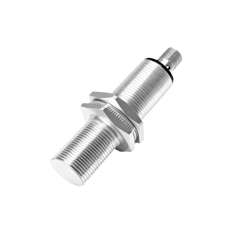
The schematic also includes essential protective components. Series resistors limit current to the oscillator and output transistor. Zener diodes are almost universally present for over-voltage protection and voltage regulation. Reverse polarity protection diodes safeguard the circuit from damage if the power supply leads are accidentally connected backwards. Additionally, a metal shield, often called a Faraday shield or a ferrite screen, surrounds the coil. This shield focuses the electromagnetic field forward and crucially makes the sensor immune to the influence of other metals surrounding its sides, a feature known as "flush mounting" capability.
Understanding the schematic clarifies several key sensor specifications. The sensing distance is determined by the coil design, oscillator power, and the trigger's sensitivity. The switching frequency is limited by the response time of the oscillator damping and the speed of the output stage. The choice of output type (NPN/PNP, NO/NC) is a function of the output stage's transistor configuration and wiring in the schematic.
In summary, the inductive proximity sensor schematic reveals an elegant application of electromagnetic principles and solid-state electronics. From the generation of the high-frequency field by the LC oscillator to the precise switching action governed by the Schmitt trigger, each stage plays a critical role in providing a robust and reliable binary signal for the presence or absence of a metallic object. Mastery of this schematic empowers engineers to select, integrate, and troubleshoot these sensors effectively in complex automation systems.