Square proximity sensors are widely used in industrial automation for non-contact detection of metallic objects. Understanding the correct wiring is crucial for ensuring reliable operation and system safety. This guide provides a detailed wiring diagram and step-by-step instructions for connecting square proximity sensors in various configurations.
Typically, a square proximity sensor has three or four wires, depending on whether it is a PNP (sourcing) or NPN (sinking) type. The common wire colors are brown for positive voltage, blue for negative or ground, black for output signal, and sometimes white for a second output or diagnostic function. Always refer to the manufacturer's datasheet for specific wire assignments, as colors can vary.
For a standard three-wire DC sensor, follow this basic wiring diagram:
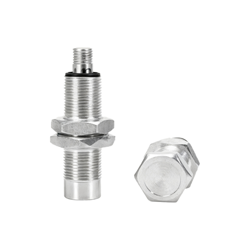
1. Connect the brown wire to the positive terminal of the DC power supply (usually +12V to +24V).
2. Connect the blue wire to the negative terminal (0V or ground) of the power supply.
3. Connect the black wire to the load, such as a programmable logic controller (PLC) input, relay, or indicator light. The load's other terminal should be connected to the power supply's negative side for PNP sensors, or positive side for NPN sensors, completing the circuit.
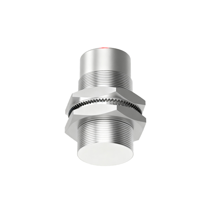
In a PNP configuration, the sensor outputs a positive voltage when activated, making it suitable for sinking input modules. In contrast, an NPN sensor outputs a negative voltage, ideal for sourcing input modules. Ensure compatibility with your control system to avoid damage. For four-wire sensors, the additional wire often provides a complementary output or diagnostic signal, allowing for more complex control logic or fault detection.
When wiring multiple sensors, use a common power supply to reduce noise and simplify installation. Route sensor cables away from high-voltage lines and motors to prevent electromagnetic interference. Shielded cables are recommended for long runs or noisy environments. Always disconnect power before making connections, and use proper terminals or connectors to secure wires, avoiding loose connections that can cause malfunctions.
Testing the wiring is essential. After connections are made, apply power and bring a metal target within the sensor's sensing range. The output LED should illuminate, and the load should activate. If not, double-check the wiring against the diagram and verify the power supply voltage. Common issues include reversed polarity, incorrect load connection, or insufficient sensing distance.
Square proximity sensors are durable, but proper wiring extends their lifespan and ensures accurate detection. Regular maintenance, such as checking for loose wires or corrosion, helps prevent downtime in automated systems. By following this wiring guide, engineers and technicians can integrate these sensors efficiently into machinery, conveyor systems, or safety applications, enhancing productivity and reliability.
For advanced setups, consider using junction boxes or interface modules to organize wiring, especially in control panels with multiple sensors. Label all wires clearly for easy troubleshooting. Remember that environmental factors like temperature, humidity, and vibration can affect performance, so choose sensors with appropriate IP ratings and wire types for your application.
In summary, a clear wiring diagram and adherence to standards are key to successful square proximity sensor installation. Always prioritize safety by following local electrical codes and manufacturer guidelines. With correct wiring, these sensors provide precise, non-contact detection that is essential in modern industrial automation.