Proximity switch sensors are essential components in modern industrial automation, enabling non-contact detection of objects. Proper wiring of their circuit boards is critical for reliable operation. This guide provides a step-by-step approach to connecting a proximity switch sensor circuit board, covering key considerations for electrical engineers and technicians.
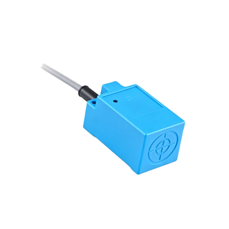
First, ensure safety by disconnecting all power sources. Verify the sensor type—inductive, capacitive, or ultrasonic—as wiring varies by model. Most proximity switches have three wires: brown (positive), blue (negative), and black (output). For DC sensors, connect the brown wire to the positive supply terminal (typically +24V DC) and the blue wire to the negative or ground terminal. The black wire links to the load, such as a PLC input or relay. For AC sensors, connect the brown wire to the live terminal and the blue wire to the neutral, with the black wire again handling the output.
Mount the sensor securely, maintaining the recommended sensing distance—usually 1-2mm for inductive types. Avoid metal interference nearby, which can cause false triggers. Use shielded cables for noisy environments, grounding the shield at one end to prevent ground loops. Check the circuit board for labeled terminals (e.g., V+, V-, OUT) and match wires accordingly. If the board includes diagnostics LEDs, verify they illuminate upon power-up to confirm correct voltage.
For multi-sensor setups, wire sensors in parallel to avoid overloading the power supply. Calculate total current draw: sum each sensor’s quiescent current and ensure the supply exceeds this by 20%. If using PNP (sourcing) sensors, connect the output to the load’s positive side; for NPN (sinking) sensors, link to the load’s negative side. Always refer to the datasheet for voltage and current ratings—exceeding these can damage the board.
Testing is crucial. Apply power and use a multimeter to check output voltage. Trigger the sensor with a target object; the output should switch states (e.g., from 0V to 24V for PNP). If issues arise, inspect connections for loose wires or shorts. For integrated circuit boards with amplification or timing functions, adjust potentiometers or DIP switches as needed—for instance, to set delay-on or hysteresis.
In summary, wiring a proximity switch sensor circuit board requires attention to polarity, load matching, and environmental factors. Proper installation ensures longevity and precision in applications like conveyor systems or robotic arms. Always follow manufacturer guidelines and industry standards, such as IEC 60947-5-2, for safe and effective deployment.