Proximity sensors are fundamental components in modern industrial automation, providing non-contact detection of metallic and, in some cases, non-metallic objects. Their reliability is paramount for ensuring smooth production flow, precise positioning, and safety in systems ranging from assembly lines to robotic cells. However, signal instability—manifesting as intermittent detection, false triggers, or erratic output—is a common and often costly challenge for maintenance engineers and system integrators. This article delves into the root causes of this instability and presents practical, field-tested solutions.
The primary culprit behind unstable signals is electromagnetic interference (EMI). Industrial environments are saturated with EMI sources: variable frequency drives (VFDs), welding equipment, large motors, and communication cables. Proximity sensors, especially inductive types, can act as antennas, picking up this noise which then corrupts the clean switching signal. The interference often couples into the sensor's output wiring or its power supply lines. A telltale sign of EMI is sporadic malfunction that correlates with the operation of other heavy machinery nearby.
Environmental factors constitute another major category. Metallic dust or conductive shavings accumulating on the active face of an inductive sensor can alter its sensing field, causing it to latch on or behave unpredictably. For capacitive sensors, variations in ambient humidity or the presence of non-target materials (like dust or foam) can change the dielectric constant, leading to drift and false detection. Extreme temperature fluctuations can also affect the oscillator circuit within the sensor, shifting its trigger point.
Installation and mechanical issues are frequently overlooked. Incorrect mounting, such as insufficient flush-mounting clearance for shielded inductive sensors, can cause the sensor to detect the mounting bracket itself. Vibration can lead to physical movement of the sensor, changing the gap to the target, or cause intermittent connection failures in wiring terminals. Using a sensor with an inadequate sensing range for the application forces it to operate at its limit, where minor variations in target position or material can cause dropouts.
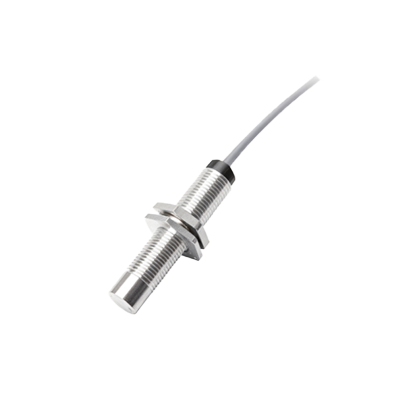
The target object itself can be a source of instability. Variations in the target's material grade, surface condition (e.g., rust, paint, plating), or size can affect the sensor's effective switching distance. For instance, different grades of stainless steel have varying permeability, leading to inconsistent detection points. Small or narrow targets may not provide enough surface area for reliable switching, especially at longer distances.
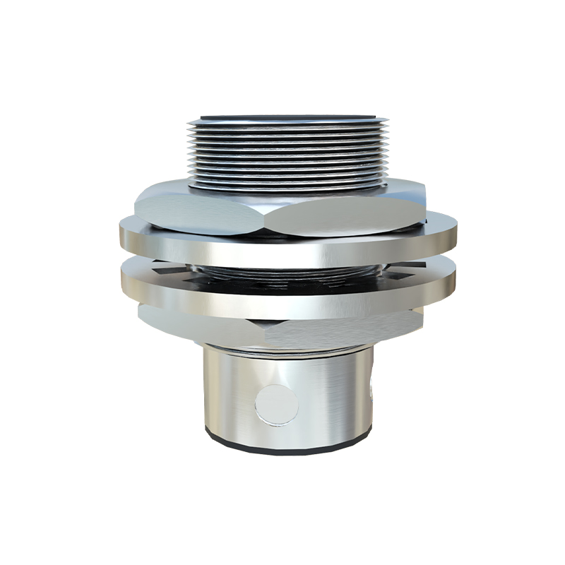
Power supply problems are a classic engineering headache. Voltage sags or spikes on the DC supply line, often caused by inrush currents from solenoids or other actuators sharing the same circuit, can reset or disrupt sensor electronics. An underpowered or poorly regulated power supply may not maintain the voltage within the sensor's specified operating range, particularly under load.
Addressing these issues requires a systematic approach. To combat EMI, implement robust shielding and grounding practices. Use shielded cables, with the shield properly grounded at the control panel end only. Physically separate sensor cables from power lines, running them in separate conduits or trays. Installing ferrite cores on the sensor cable near the connector can suppress high-frequency noise. For severe cases, consider using sensors with built-in noise immunity features or analog output types with filtering.
Maintain a clean operating environment. Regularly clean the sensor face from buildup. For challenging environments, select sensors with appropriate IP (Ingress Protection) ratings; for example, IP67 for washdown areas or IP69K for high-pressure cleaning. Temperature-compensated sensors are available for applications with wide thermal swings.
Ensure precise mechanical installation. Follow the manufacturer's guidelines for mounting clearances. Use vibration-proof mounting hardware and ensure all electrical connections are tight. Employ sensing margin checks: the actual operating distance should be 60-70% of the sensor's rated nominal range to account for variations.
Standardize target materials and conditions where possible. If material varies, select a sensor with a factor of safety or use a factor-correction to derate the nominal sensing distance. For problematic small targets, choose a sensor with a reduced sensing range or a focused field.
Implement a stable, dedicated power supply for sensitive sensor clusters. Use line conditioners or separate transformers if necessary. Incorporate protective circuits like flyback diodes for inductive loads (coils, relays) on the same circuit to suppress voltage spikes.
Finally, sensor selection is critical. For metal detection, inductive sensors are robust. For non-metallics, capacitive or ultrasonic sensors are suitable. In high-noise environments, consider DC sensors with a short-circuit protection feature (typically 3-wire types) over 2-wire AC/DC types, as they generally offer better noise immunity. Analog output sensors (4-20mA or 0-10V) can provide a continuous signal that is less prone to chatter compared to a digital switch, with threshold detection handled in the PLC.
Proactive maintenance, including periodic inspection of sensing distances and output signals