In industrial automation and precision metrology, laser displacement sensors are indispensable tools for non-contact measurement of distance, thickness, and vibration. However, a common and often underestimated challenge arises when these sensors are deployed to measure inclined or sloped surfaces. The fundamental operating principle of a triangulation-based laser displacement sensor assumes an ideal scenario where the target surface is perpendicular to the sensor's optical axis. When this condition is not met, as with an inclined plane, significant measurement errors can occur, compromising data integrity and process control.
The core of the issue lies in the geometry of triangulation. The sensor projects a laser spot onto the target surface, and a receiving lens images this spot onto a position-sensitive detector (PSD or CMOS). The calculated displacement is based on the precise location of this imaged spot. On a perpendicular surface, the reflected light returns along a predictable path. On an inclined surface, the angle of incidence changes, causing the reflected beam to deviate from its expected trajectory. This phenomenon, known as the cosine error, introduces a systematic offset. The measured value is effectively the distance to the surface along the sensor's line-of-sight, not the true perpendicular distance. For a plane inclined at angle θ, the error is proportional to (1/cos θ - 1). At a 10-degree inclination, the error is approximately 1.5%; at 30 degrees, it escalates to about 15.5%, which is often unacceptable for precision applications.
Beyond the cosine error, the inclination angle critically affects the intensity and quality of the reflected light signal. If the surface is highly specular (shiny), the reflected beam may be directed completely away from the receiving lens, resulting in a loss of signal or "dropout." Even with diffuse surfaces, the effective light intensity captured by the receiver is reduced, lowering the signal-to-noise ratio and potentially causing unstable readings. Furthermore, the shape of the laser spot on the detector can become elliptical or distorted, challenging the centroid calculation algorithms within the sensor's processor.
To mitigate these challenges, engineers must adopt a systematic approach. The primary and most effective strategy is meticulous sensor alignment. Whenever possible, the sensor should be mounted so that its optical axis is perpendicular to the inclined surface. This may require custom brackets or adjustable mounts. When physical realignment is impossible due to spatial constraints, advanced sensors offer a built-in "tilt correction" function. This feature allows the user to input the known inclination angle of the target surface, and the sensor's internal firmware automatically applies a geometric correction to the raw distance data, compensating for the cosine error.
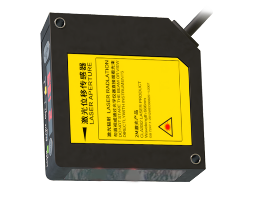
Sensor selection is equally crucial. For applications involving variable or unknown angles, a 2D laser profile sensor or a line laser scanner is a superior choice. Instead of measuring a single point, these devices capture an entire cross-sectional profile of the target. Software algorithms can then fit a line or shape to the profile data and extract precise measurements (like height or width) that are largely independent of the overall tilt of the object. For point sensors, choosing a model with a larger "acceptable tilt angle" specification, often achieved through a wider receiver lens arrangement, provides more operational flexibility.
Environmental and surface properties must also be considered. Applying a temporary matte coating or using a diffuse target plate attached to the sloped surface can standardize reflectivity and improve signal stability. The installation environment should be assessed for ambient light interference, which can exacerbate the low-signal issues associated with inclined measurements. Using sensors with modulated laser light and narrow-band optical filters helps reject ambient noise.
In practice, a thorough on-site validation is non-negotiable. After installation and configuration, measurements should be benchmarked against a known reference, such as a gauge block or a coordinate measuring machine (CMM) reading, across the expected range of inclinations and positions. This process verifies the effectiveness of the chosen compensation method and establishes a known uncertainty budget for the measurement system.
In conclusion, while inclined surfaces present a non-ideal condition for laser displacement sensors, the errors are predictable and manageable. Success hinges on understanding the underlying optical principles, carefully selecting and aligning the hardware, utilizing available software corrections, and rigorously validating the system performance. By addressing the斜面 challenge proactively, engineers can ensure their laser sensors deliver the high-accuracy, reliable data required for demanding quality control, robotic guidance, and research applications.