In industrial automation and control systems, proximity sensors play a critical role in detecting the presence or absence of objects without physical contact. Among various types, four-wire proximity sensors are widely favored for their versatility, combining both normally open (NO) and normally closed (NC) outputs in a single device. This article provides a comprehensive guide to wiring four-wire proximity sensors, ensuring reliable operation and safety in electrical installations.
A typical four-wire proximity sensor consists of four distinct wires, each serving a specific function. These wires are color-coded according to international standards, though variations may exist based on manufacturer specifications. Commonly, the wires include:
- Brown wire: Connected to the positive DC supply voltage (typically +24V DC).
- Blue wire: Connected to the negative DC supply voltage (0V or ground).
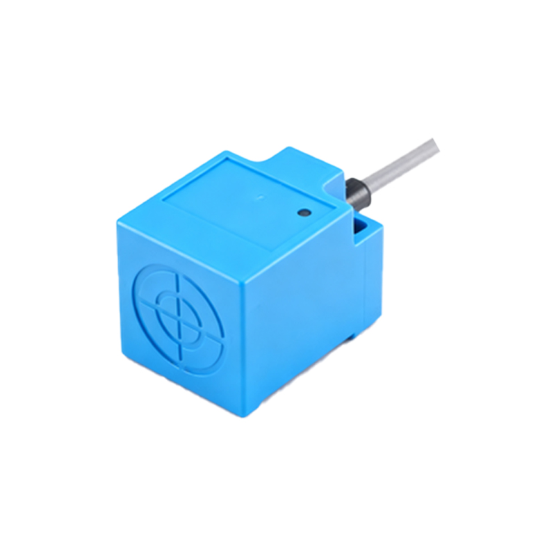
- Black wire: Represents the normally open (NO) output signal.
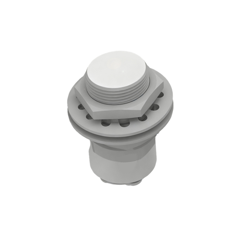
- White wire: Represents the normally closed (NC) output signal.
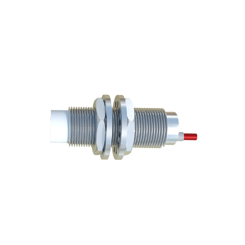
Before starting the wiring process, it is essential to verify the sensor's datasheet for exact voltage ratings, current capacity, and wire color codes. Incorrect connections can lead to sensor damage, malfunction, or safety hazards.
Step-by-Step Wiring Procedure:
1. Power Supply Connection: Connect the brown wire to the positive terminal of the DC power supply (e.g., +24V DC). Ensure the voltage matches the sensor's rated operating range. Connect the blue wire to the negative terminal or ground of the power supply. Use shielded cables in environments with electrical noise to prevent interference.
2. Output Connections: The black wire (NO output) and white wire (NC output) are connected to the load or control device, such as a programmable logic controller (PLC), relay, or indicator. For the NO output, the circuit remains open when no target is detected and closes upon detection. Conversely, the NC output circuit is closed when no target is present and opens upon detection.
3. Load Integration: Connect the NO or NC output wires to the input module of the PLC or relay coil. Ensure the load current does not exceed the sensor's maximum switching capacity. A common practice is to include a protective fuse or circuit breaker in series with the power supply to prevent overcurrent situations.
4. Wiring Considerations: Maintain proper cable management by routing wires away from high-voltage lines, motors, or sources of electromagnetic interference (EMI). Use conduit or cable trays in harsh industrial environments to protect against mechanical damage, moisture, and dust.
5. Testing and Verification: After wiring, power on the system and test the sensor by introducing a target object within its sensing range. Verify that the NO and NC outputs respond correctly using a multimeter or PLC monitoring software. Adjust the sensor's position if necessary to achieve optimal detection accuracy.
Common Applications and Benefits:
Four-wire proximity sensors are ideal for applications requiring dual output options, such as conveyor systems, packaging machinery, and safety interlocks. Their key advantages include flexibility in control logic, reduced wiring complexity compared to using multiple sensors, and enhanced diagnostic capabilities through both NO and NC signals.
Troubleshooting Tips:
- If the sensor fails to operate, check power supply polarity and voltage levels.
- Ensure the target material is compatible with the sensor's sensing technology (inductive, capacitive, or ultrasonic).
- Inspect for loose connections or damaged wires, especially in vibrating environments.
- Consult the manufacturer's guidelines for environmental limits, such as temperature and humidity ranges.
By following this wiring guide, engineers and technicians can ensure efficient and safe integration of four-wire proximity sensors into industrial systems. Proper installation not only extends sensor lifespan but also contributes to overall system reliability and productivity.