Two-wire proximity sensors are ubiquitous components in modern industrial automation, offering a simplified and cost-effective solution for non-contact object detection. Unlike their three-wire counterparts, these sensors integrate the switching element directly into the power line, eliminating the need for a separate load wire. This design makes them exceptionally easy to install and wire, particularly in retrofit applications or where cabinet space is at a premium. Their primary function is to detect the presence or absence of metallic (inductive type) or non-metallic (capacitive type) targets without physical contact, thereby ensuring reliability and longevity in demanding environments.
The fundamental operating principle hinges on their integration into the load circuit. A two-wire sensor is connected in series with the load (e.g., a PLC input, relay coil, or indicator lamp). When no target is present, a small leakage current, typically under 1.5 mA, flows through the sensor. This current is insufficient to activate the load, keeping it in the "OFF" state. Upon detecting a valid target within its sensing range, the internal solid-state switch closes (for normally open, NO, types), allowing the full operating current to pass through to energize the load. It is crucial to understand that the sensor itself requires a minimum holding current to remain operational after switching, which must be considered during load selection.
Correct wiring is paramount for reliable operation. The two wires are designated as Brown (or +) and Blue (or -) following the international IEC standard. The Brown wire connects to the positive DC supply voltage (typically 10-30V DC) or the live AC terminal. The Blue wire connects to the load, and the other side of the load returns to the negative DC supply or neutral AC line. A critical consideration is the voltage drop across the sensor when active, often ranging from 2 to 4 volts. This drop must be subtracted from the supply voltage to ensure the load receives adequate voltage to operate. For instance, with a 24V DC supply and a 3V sensor drop, the load effectively sees 21V. Always consult the manufacturer's datasheet for specific values.
Load compatibility is the most significant factor in application success. The connected load must fall within the sensor's specified minimum and maximum current ratings. If the load current is below the sensor's minimum required current, the sensor may not switch off reliably or may chatter, leading to erratic behavior. Conversely, exceeding the maximum current rating will damage the sensor. Resistive loads like indicator lamps are straightforward. Inductive loads (relays, solenoids) require careful attention; using a protective circuit like a flyback diode across the DC coil is often recommended to suppress voltage spikes that could damage the sensor's internal electronics. For capacitive loads or very light loads below the minimum current, an external "bleeder" or "wetting" resistor can be placed in parallel with the load to ensure the minimum current flows.
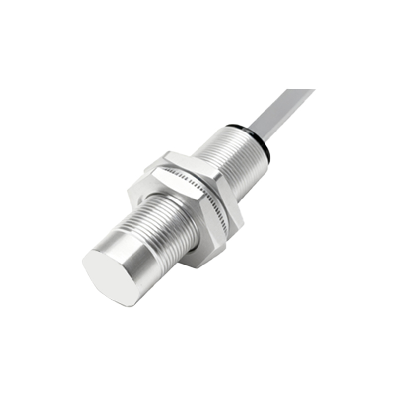
When selecting and applying a two-wire proximity sensor, engineers must evaluate several key parameters:
1. Sensing Type & Range: Choose inductive (for metals) or capacitive (for non-metals, liquids). The nominal sensing distance (Sn) is specified for a standard target; always account for reduction factors for different metals.
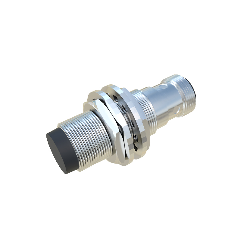
2. Supply Voltage: Ensure compatibility with your system's DC or AC voltage. Many modern sensors offer wide-range DC (10-30V) for flexibility.
3. Current Ratings: Verify the load current is between the specified Min. and Max. operating current. The off-state leakage current must also be considered for sensitive PLC inputs.
4. Switching Frequency: The maximum number of on/off cycles per second. This must be higher than the required cycle speed of your application.
5. Environmental Factors: Consider IP rating for dust/water ingress, temperature range, and resistance to chemicals or welding spatter.
6. Output Function: Normally Open (NO) is most common. Normally Closed (NC) types are available but less frequent.
A common application pitfall is directly connecting a two-wire sensor to a programmable logic controller (PLC) digital input. Many PLC inputs have high impedance, drawing current below the sensor's minimum requirement. This leads to a residual voltage at the input when the sensor is "off," potentially causing the PLC to read a false "on" signal. The solution is to add a dummy load resistor across the PLC input terminals to draw the necessary minimum current. Calculate the resistor value using Ohm's Law (R = V/I), where V is the supply voltage and I is the sensor's minimum current, ensuring the resistor's power rating (P=V²/R) is adequate.
In summary, the successful deployment of two-wire proximity sensors relies on a clear understanding of their series-circuit operation,