In the realm of industrial automation and control systems, proximity sensors are indispensable components for detecting the presence or absence of objects without physical contact. Among the various types, the 3-wire DC inductive and capacitive proximity sensors are most prevalent, and their operation is fundamentally defined by their output transistor configuration: NPN or PNP. This distinction, while seemingly simple, is critical for proper system integration, safety, and functionality. This article delves into the operational principles, wiring differences, and practical application guidelines for NPN and PNP proximity switches.
At the core of a 3-wire DC proximity sensor lies a solid-state switching element, typically a transistor. The sensor itself requires a DC power supply, commonly 10-30 VDC, provided via two wires: brown (or red) for positive (+) and blue for negative (-) or common. The third wire, usually black (or sometimes white or gray), is the output signal wire. The designation "NPN" or "PNP" refers to the type of bipolar junction transistor (BJT) used for the output switch. This designation dictates the switching logic and the required circuit configuration.
An NPN sensor utilizes a negative-switching transistor. In its normal state (no target detected), the output transistor is off, and the output wire is in a high-impedance state (effectively open). When a target enters the sensing range, the internal circuitry activates the NPN transistor, allowing current to flow from the load into the sensor's output terminal and then out through the blue (common) wire to the negative supply. In simpler terms, the NPN sensor sinks current to ground. It provides a path to negative (0V) when active. Therefore, the load (e.g., a PLC input, relay coil, or indicator lamp) must be connected between the positive supply voltage and the sensor's output wire. The sensor acts as a switch to the negative rail.
Conversely, a PNP sensor employs a positive-switching transistor. In its normal state, the output is off (open). Upon detection, the PNP transistor turns on, allowing current to flow from the sensor's output terminal to the load and then to the negative supply. The PNP sensor sources current from the positive supply. It provides a path to positive voltage (+V) when active. Consequently, the load must be connected between the sensor's output wire and the negative supply (0V). The sensor acts as a switch to the positive rail.

This fundamental difference has significant implications for wiring and compatibility. A common mnemonic is "PNP = Positive-switched, NPN = Negative-switched." Another is "PNP: Switches Positive; NPN: Switches Negative." The choice between NPN and PNP is not about performance but about the electrical interface of the control system. Historically, and often regionally, preferences exist. For instance, PNP sensors (sourcing outputs) are frequently standard in Europe and with many PLCs from European manufacturers, as they traditionally favored positive logic for inputs. NPN sensors (sinking outputs) have been more common in Asia and are compatible with many Japanese-origin PLCs.
From a practical engineering standpoint, selecting the correct type is paramount. Connecting a PNP sensor to a circuit designed for an NPN sensor, or vice versa, will result in malfunction or no operation. Modern programmable logic controllers (PLCs) often have input circuits that can be configured or are compatible with both types, typically by providing a common terminal that can be wired to either +V or 0V. However, for discrete relay or valve coil interfaces, the distinction remains absolute.
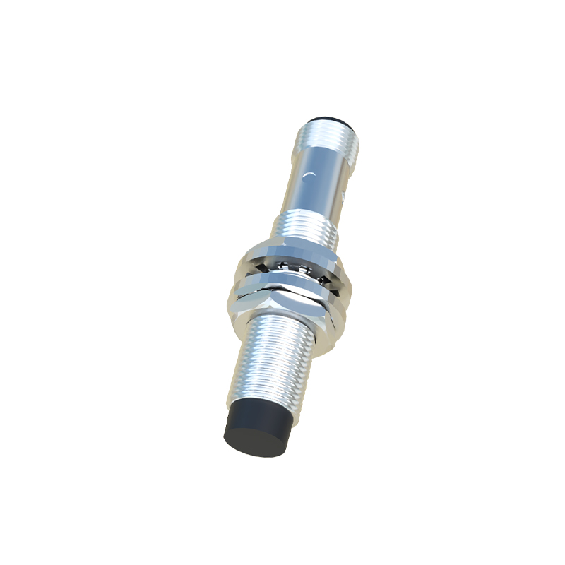
Safety and fail-safe considerations also play a role. Some designs utilize a normally-closed (NC) output configuration instead of the standard normally-open (NO). An NPN-NO sensor becomes a conducting sink when activated, while an NPN-NC sensor is a conducting sink when not activated. The same logic applies to PNP. Understanding this is crucial for designing fail-safe systems where a wire break or power loss should cause a safe state.
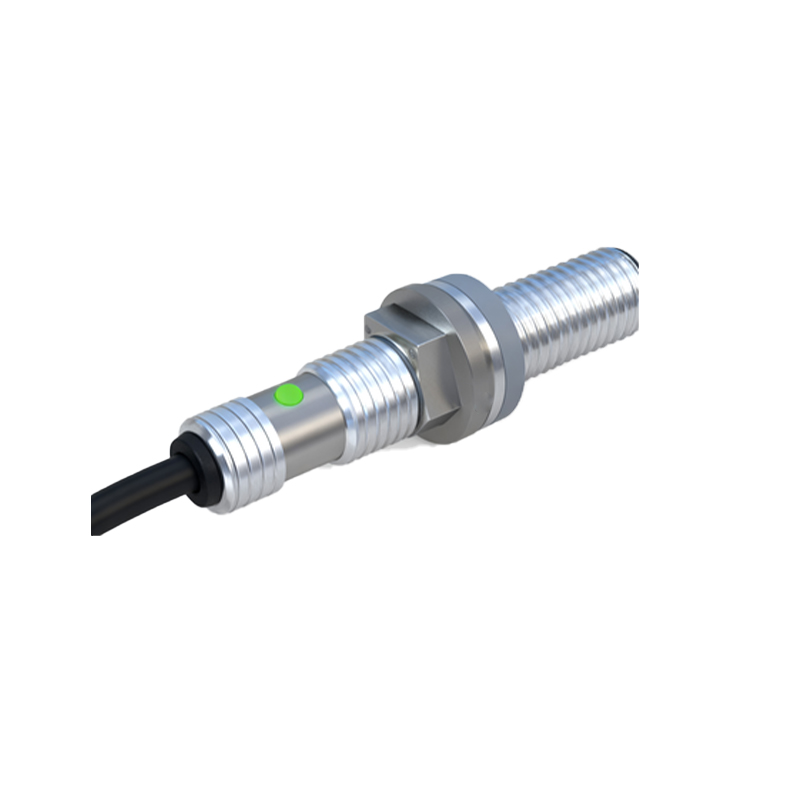
In summary, the NPN vs. PNP decision hinges on the required current flow path for the controlled load. Always consult the sensor datasheet and the controller's input specifications. As a best practice, ensure consistent use within a panel or machine to avoid wiring complexity and potential errors. With a clear grasp of these principles—that NPN sinks to common and PNP sources from positive—electrical engineers can confidently specify, wire, and troubleshoot these essential components, ensuring robust and reliable automation system performance.