In industrial automation and control systems, proximity sensors are indispensable components for detecting the presence or absence of an object without physical contact. Among the various types available, 2-wire proximity sensors are widely favored for their simplicity and cost-effectiveness in installation. Unlike their 3-wire or 4-wire counterparts, which have separate power, ground, and signal lines, a 2-wire sensor integrates the switching function directly into the power loop. This design reduces wiring complexity and minimizes space requirements in control panels. However, proper wiring is crucial to ensure reliable operation and prevent damage to the sensor or connected equipment. This guide provides a step-by-step approach to wiring a 2-wire proximity sensor, covering key principles, common pitfalls, and best practices for engineers and technicians.
First, understand the basic operating principle of a 2-wire proximity sensor. It functions as a switch in series with the load (e.g., a PLC input, relay, or indicator light) within a DC or AC circuit. The sensor typically has two terminals: one for connecting to the power supply (positive or line voltage) and the other for connecting to the load. When no target is detected, the sensor maintains a high impedance state, allowing only a small leakage current (usually a few milliamps) to flow. Upon detecting a target within its sensing range, the sensor switches to a low impedance state, enabling sufficient current to power the load. This behavior is similar to a normally open (NO) or normally closed (NC) contact, depending on the sensor model. Always refer to the manufacturer’s datasheet for specific details, as wiring errors can lead to malfunction or permanent failure.
Before starting the wiring process, gather the necessary tools and components: a 2-wire proximity sensor (ensure it matches the voltage and current ratings of your application), a suitable power supply (commonly 10-30V DC or 20-250V AC), a load device, insulated wire strippers, screwdrivers, and possibly a multimeter for verification. Safety is paramount—disconnect all power sources and follow lockout/tagout (LOTO) procedures to prevent electrical hazards. Identify the sensor’s terminals; they are often labeled as “+” and “−” for DC sensors or “L1” and “L2” for AC sensors, though some may use color-coded wires (e.g., brown for positive/line and blue for negative/load).
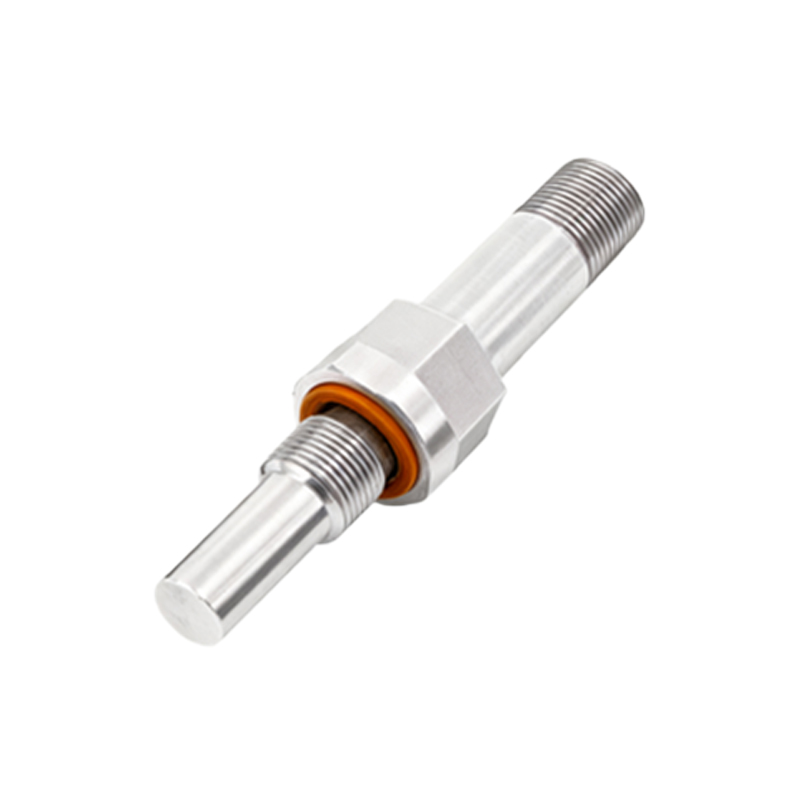
For a typical DC circuit, follow these steps:
1. Connect the positive terminal of the DC power supply to the positive terminal (or brown wire) of the sensor.
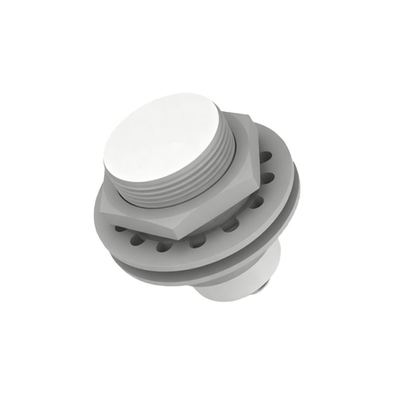
2. Connect the negative terminal (or blue wire) of the sensor to one terminal of the load (e.g., the input of a PLC digital module).
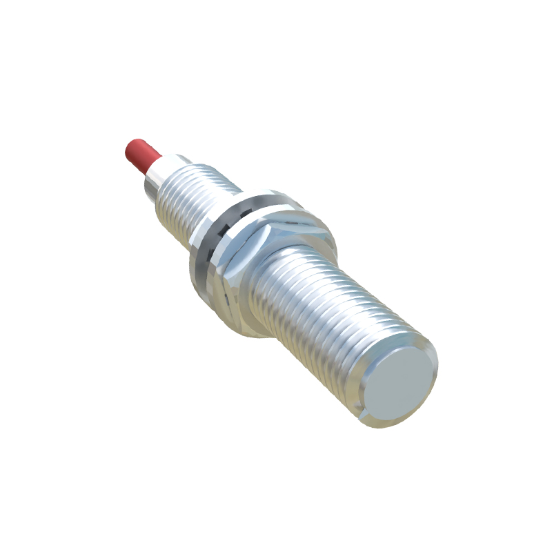
3. Connect the other terminal of the load to the negative terminal of the power supply, completing the series circuit.
Ensure polarities are correct, as reverse connection can damage DC sensors. For AC circuits, the wiring is similar but polarity-insensitive: connect one side of the AC power source to the sensor’s line terminal, then link the sensor’s load terminal to the load, and finally return the load to the other side of the AC source.
Critical considerations include voltage drop and leakage current. Since the sensor is in series with the load, its internal resistance causes a voltage drop when activated. This drop must be accounted for to ensure the load receives adequate voltage. For instance, if using a 24V DC supply and a sensor with a 3V drop, the load effectively gets 21V—verify that this meets the load’s minimum operating voltage. Leakage current (typically 1-2 mA for DC sensors) flows even when the sensor is off. If the load has a high impedance (e.g., some PLC inputs), this leakage might be enough to falsely activate the load. To mitigate this, connect a bypass resistor (bleeder resistor) in parallel with the load to shunt the leakage current. Calculate the resistor value using Ohm’s law: for example, with 2 mA leakage and a 24V system, a 12 kΩ resistor can dissipate the current without affecting normal operation.
Common wiring mistakes to avoid include overloading the sensor (exceeding its maximum current rating), using an incompatible power supply (e.g., AC for a DC-only sensor), and neglecting environmental factors like moisture or electromagnetic interference. Always secure connections with proper terminals to prevent loose wires, which can cause intermittent faults. After wiring, test the system: apply power, bring a target within the sensing range, and check if the load activates. Use a multimeter to measure voltage across the load and current through the circuit, comparing readings with the datasheet specifications.
In summary