Proximity sensors are vital components in modern automation, robotics, and countless electronic devices. They detect the presence or absence of an object within a specific range without physical contact. Understanding their internal architecture is key to proper selection and application. This article provides a detailed breakdown of a standard proximity sensor's component diagram, explaining the function of each part in clear, technical terms.
At the heart of most inductive or capacitive proximity sensors lies the Oscillator Circuit. This circuit generates a high-frequency electromagnetic field that radiates from the sensor's active surface, typically the front face. In inductive sensors, this field is generated by a coil within an oscillator. When a metallic object enters this oscillating field, eddy currents are induced on the object's surface. These eddy currents draw energy from the oscillator, causing a reduction in its amplitude. This amplitude change is the primary detection signal.
The Detection Circuit is responsible for monitoring the oscillator's state. It continuously measures the amplitude of the oscillations. Once the amplitude drops below a predefined threshold—indicating an object is within the sensing range—the detection circuit triggers a signal. This circuit is finely tuned to the sensor's specified sensing distance and is responsible for its hysteresis, which prevents output chatter when an object is at the exact detection boundary.
Following detection, the signal is passed to the Output Circuit. This component conditions the raw detection signal into a usable output for control systems. Common output types include:
Transistor Outputs (NPN or PNP): These provide a digital ON/OFF signal (sinking or sourcing) to programmable logic controllers (PLCs) or other digital inputs.
Analog Outputs (0-10V, 4-20mA): These provide a continuous signal proportional to the distance of the object from the sensor, useful for measuring position or thickness.
Relay Outputs: Used for switching higher-power AC or DC loads directly.
The output circuit is protected by internal components like Transient Voltage Suppressors (TVS) or Zener Diodes to guard against voltage spikes, reverse polarity, and short-circuit conditions, ensuring longevity in industrial environments.
Power for all internal electronics is managed by the Power Supply Regulator. Proximity sensors often operate on a wide range of DC voltages (e.g., 10-30V DC). This regulator steps down and stabilizes the incoming voltage to the precise levels required by the oscillator, detection, and output circuits, ensuring consistent performance despite line voltage fluctuations.
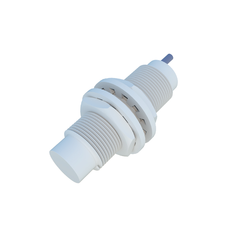
The Housing is a critical structural component. It is typically made of metal (like nickel-plated brass or stainless steel) for inductive sensors or plastic for capacitive sensors. The housing provides environmental protection, specified by an IP (Ingress Protection) rating (e.g., IP67), guarding against dust, water, and mechanical impact. It also shields the internal electronics from external electromagnetic interference (EMI) and contains the sensing face.
For inductive sensors, the Ferrite Core (often part of the oscillator coil assembly) concentrates the electromagnetic field at the sensing face, increasing sensitivity and defining the sensing range. The sensing face itself is often a wear-resistant material that allows the field to pass through.
Finally, the Indicator LED(s) are simple but essential. They provide visual confirmation of the sensor's operational status—usually power ON and output activation—crucial for installation, troubleshooting, and maintenance.
In summary, a proximity sensor is a sophisticated integration of electromagnetic theory and solid-state electronics. The oscillator creates a detection field, the detection circuit senses disturbances, the output circuit interfaces with the outside world, and the power regulator and housing ensure reliable operation. Reading a component diagram with these elements in mind allows engineers and technicians to fully understand the sensor's capabilities, limitations, and integration requirements, leading to more robust and reliable system designs.