In the automotive and industrial sectors, vehicle speed sensors (VSS) paired with proximity switches are critical for monitoring rotational speed, enabling precise control in systems like anti-lock braking, transmission management, and speedometers. A properly executed wiring diagram ensures reliability, safety, and optimal performance. This guide details the standard wiring practices for inductive proximity switches commonly used in speed sensing applications.
Proximity switches for speed sensing are typically inductive-type sensors, detecting metallic targets (such as gear teeth or encoder wheels) without physical contact. They generate a digital pulse signal corresponding to target movement. The core components include the sensor itself, a power supply, a load (often an ECU or counter), and interconnecting cables.
A standard three-wire DC inductive proximity switch is most prevalent. The wiring configuration is as follows:
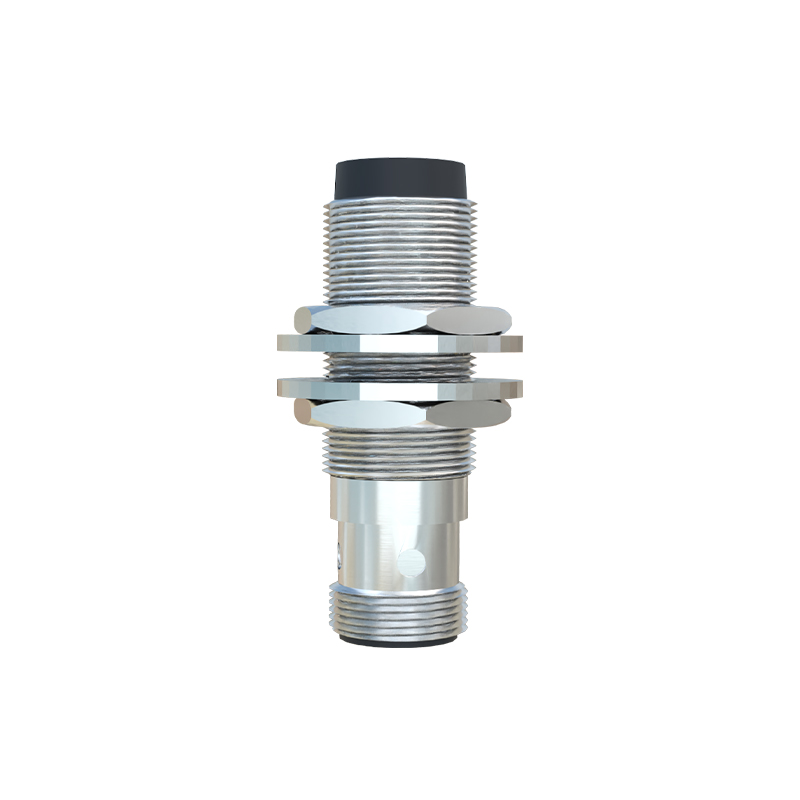
1. Brown Wire: Connect to the positive terminal of the DC power supply (typically +12V or +24V DC, as per sensor specifications).
2. Blue Wire: Connect to the negative terminal (0V) of the DC power supply and the common ground of the system.
3. Black Wire: This is the signal output wire. It connects to the input terminal of the load (e.g., the vehicle's ECU or a dedicated speed module).
The sensor operates on the principle of electromagnetic induction. When a metallic target approaches the active face, it dampens the sensor's internal oscillator, triggering a solid-state switch. For an NPN (sinking) output type, the black wire switches the load connection to ground (0V), common in European and Asian designs. For a PNP (sourcing) output type, the black wire switches the load connection to the positive supply voltage, often found in North American systems. The load is permanently connected to the opposite supply rail.
Crucial Wiring Practices:
Power Supply: Ensure a stable, regulated DC supply within the sensor's rated voltage range (e.g., 10-30V DC). Incorporate a fuse (1-2A) in the positive line near the power source for protection.
Shielding & Routing: In electrically noisy environments (near motors, ignition systems), use shielded cables. Connect the cable shield to a robust earth ground at one end only (preferably the controller end) to prevent ground loops. Route sensor cables away from high-current power lines.
Load Compatibility: Verify the input characteristics of the ECU or counter. The sensor's output current rating must be sufficient to drive the load. A pull-up or pull-down resistor may be required for some controller inputs to ensure a defined logic state.
Installation: Maintain the specified sensing distance (usually 1-4 mm for ferrous targets). Ensure the target material and size meet sensor requirements. Secure all connections with appropriate terminals, and protect connectors from moisture and vibration.
Diagnostic Steps for Faulty Signals:
1. Check power supply voltage at the sensor connector with a multimeter.
2. Verify continuity and integrity of all wires.
3. Monitor the signal wire with an oscilloscope while rotating the target. A clean, square-wave signal should be present.
4. Inspect for sensor damage or misalignment.
Adherence to a correct wiring diagram and these installation principles minimizes downtime, prevents erroneous speed readings, and extends system lifespan. Always consult the specific manufacturer's datasheet for the proximity switch and vehicle/controller manual, as terminal colors and functions can occasionally vary. Proper implementation transforms a simple wiring task into a cornerstone of system integrity.