In the realm of industrial automation and control systems, proximity switch sensors are indispensable components. Their primary function is to detect the presence or absence of an object without physical contact, offering reliability, longevity, and high-speed operation. This article delves into the schematic principles of various proximity switch sensors, providing a detailed technical breakdown for electrical engineers and industry professionals.
The core principle behind all proximity sensors is the disturbance of an electromagnetic field, an electrostatic field, or a beam of radiation. This disturbance is converted into an electrical signal by the sensor's internal circuitry, which is then processed to trigger a switching action. Schematically, a proximity sensor can be divided into three main sections: the oscillator, the detector/trigger circuit, and the output stage.
1. Inductive Proximity Sensors:
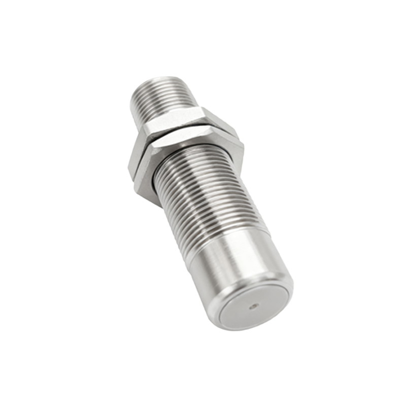
The most common type, inductive sensors, detect metallic objects. The schematic centers around a high-frequency oscillator circuit (often using a Colpitts or Hartley configuration) connected to a coil of wire that forms the sensor's active face. This coil generates a high-frequency electromagnetic field. When a metallic object enters this field, eddy currents are induced on the object's surface. These eddy currents draw energy from the oscillator, causing its amplitude to decrease. This amplitude change is detected by a subsequent circuit—typically a Schmitt trigger or a comparator. The detector circuit's output then drives the final output stage, which is usually an NPN or PNP transistor in an open-collector (or open-drain) configuration, or a solid-state relay. The schematic will clearly show the oscillator components (inductor/coll, capacitors, resistor, and an IC or transistor), the detection IC with hysteresis for stability, and the output transistor with a flyback diode for inductive load protection.
2. Capacitive Proximity Sensors:
Capacitive sensors can detect both metallic and non-metallic materials (plastics, wood, liquids) by sensing changes in capacitance. The schematic is similar in structure to the inductive type but operates differently. The sensor face acts as one plate of a capacitor, with the target object acting as the other plate (or altering the dielectric constant). The oscillator circuit is designed to be sensitive to this capacitive change. As an object approaches, the effective capacitance increases, altering the oscillator's frequency or amplitude. This shift is detected and processed. The schematic often includes a sensitivity adjustment potentiometer in the oscillator or detector stage to tune for different materials. The output stage is identical to that of inductive sensors.
3. Photoelectric Sensors:
While not always classified as "proximity" switches in the strictest sense, photoelectric sensors are ubiquitous for non-contact detection. Their schematics are distinctly different. They consist of a light emitter (usually an LED, often infrared) and a receiver (phototransistor or photodiode). In a thru-beam configuration, the emitter and receiver are separate; breaking the beam triggers the output. In a retro-reflective mode, the sensor uses a single unit and a reflector. The most common for proximity detection is the diffuse (reflective) mode, where the sensor detects light reflected from the target itself. The schematic shows the LED driver circuit (constant current for stability), the highly sensitive receiver amplifier circuit (often a transimpedance amplifier for photodiodes), and a comparator to distinguish between the presence and absence of a received signal. Advanced versions may include background suppression circuitry schematically represented by additional op-amps or dedicated ICs.
Key Schematic Symbols and Notations:
Understanding standard symbols is crucial. The sensor coil for inductive types, capacitor symbols for capacitive types, and LED/phototransistor symbols for photoelectric types are fundamental. Output configurations are critical: NPN (sinking) vs. PNP (sourcing) transistors are denoted with their emitter arrows. The presence of a diode across the output terminals indicates polarity protection or a flyback diode. IC part numbers (like LM393 for comparators, NE555 for timers) provide insight into functionality. Power supply connections, typically labeled as Vcc (10-30V DC) and GND, and the load connection (to the output transistor's collector) are always clearly marked.
Design Considerations in the Schematic:
A well-designed schematic incorporates protection and stability features. Look for:
Hysteresis in the detector circuit: Prevents output chatter when the target is at the detection boundary.
Shielding and filtering: RC networks or ferrite beads to suppress electromagnetic interference (EMI) from nearby motors or drives.
Reverse polarity protection: A series diode or a bridge rectifier at the power input.
Short-circuit and overload protection: A resistor or a current-limiting circuit in series with the output transistor.
Status Indicator LED: Often connected in parallel with the output