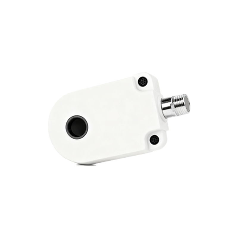
In the industrial automation of grain handling facilities, the proper functioning of unloading systems is paramount for operational efficiency and safety. A critical component within these systems is the proximity sensor, typically an inductive type, used to detect the position of the unloading tube or the presence of metallic components. A common yet often underestimated installation error is mounting the sensor too close to its target. This practice, seemingly innocuous for ensuring detection, can lead to a cascade of technical issues that compromise system reliability.
When an inductive proximity sensor is installed excessively close to a metal target, such as the tube housing or actuator, it operates within an ultra-near field. This forces the sensor into a state of permanent activation or, conversely, can cause unpredictable oscillation between on and off states due to electromagnetic saturation. The sensor's internal oscillator is designed for a specific sensing range (Sn). Operating consistently at a fraction of this nominal distance overloads the oscillator circuit, generating excessive heat. This thermal stress accelerates the aging of electronic components, particularly the output transistor, leading to premature failure. The result is not merely a faulty sensor but unplanned downtime during critical unloading operations.
Furthermore, the mechanical vibration inherent in grain unloading equipment presents another challenge. A sensor mounted with minimal clearance is highly susceptible to physical contact with the moving target due to vibration or slight misalignment. Even momentary contact can damage the sensor's sensing face or its mounting bracket. More insidiously, the accumulation of grain dust and metallic particulates, a constant in such environments, can bridge the tiny gap. This conductive buildup can create a false "target," causing the sensor to latch in a detected state even when the actual metal target has moved away. This false signal disrupts the control logic, potentially causing the unloading sequence to halt erroneously or, worse, proceed unsafely.
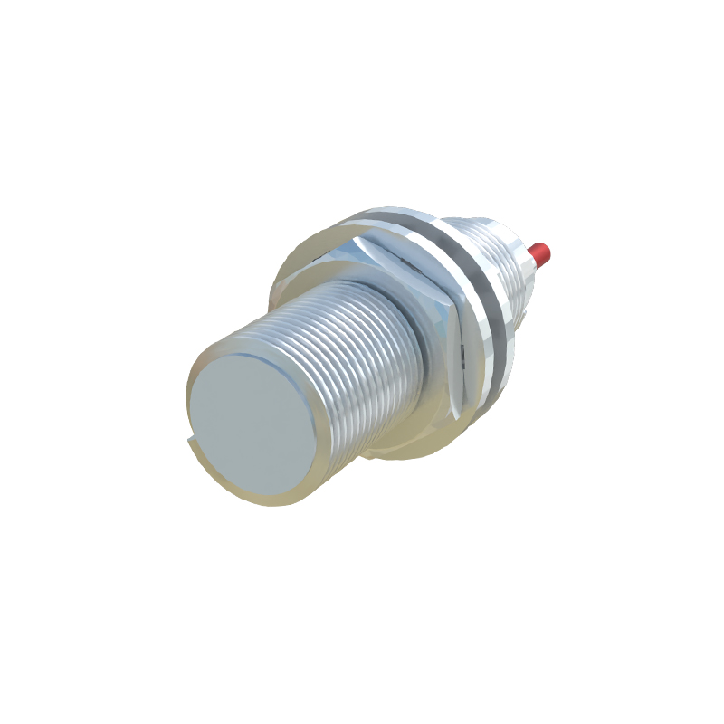
From an electrical perspective, the load on the sensor's output stage increases under near-constant activation. In DC sensors, this can lead to elevated current draw and heat dissipation. For AC sensors, the inrush current during frequent switching cycles stresses both the sensor and the controlling relay or PLC input module. The system's diagnostic capabilities are also hindered. A sensor that is always "on" provides no useful feedback on the machine's cycle, masking other potential faults like a stuck actuator or a broken mechanical linkage.
The corrective action is rooted in adherence to manufacturer specifications. The optimal installation distance is typically 0.8 times the rated sensing distance (0.8 x Sn). This provides a reliable detection margin that accounts for mechanical tolerances, thermal expansion, and vibration without pushing the sensor into its nonlinear saturation zone. For cylindrical sensors, maintaining a radial clearance from surrounding metal structures (as per datasheet guidelines) is equally crucial to prevent lateral electromagnetic interference. Regular maintenance, including cleaning the sensor face to remove dust buildup and checking mounting integrity, is essential for long-term reliability.
In conclusion, the installation of a proximity sensor in a grain unloading context is a precision task, not a mere mechanical mounting. "Closer is better" is a dangerous misconception. Ensuring the correct installation gap is a fundamental engineering practice that directly influences mean time between failures (MTBF), system safety, and overall operational throughput. A meticulously installed sensor, operating within its designed parameters, is a small but vital investment in the seamless and safe automation of bulk material handling.