In the realm of industrial automation and machine design, proximity sensors are indispensable components for non-contact detection of objects. Among their critical performance parameters, response time stands out as a pivotal factor influencing system speed, efficiency, and reliability. This article delves into the technical intricacies of proximity sensor response time, exploring its definition, determining factors, measurement methodologies, and practical strategies for optimization.
Fundamentally, the response time of a proximity sensor is the total duration required for the sensor to detect a target's presence or absence and produce a corresponding, stable output signal change. It is typically measured from the moment the target enters (or leaves) the sensor's effective sensing range to the moment the output switching element (transistor or relay) completes its state change. This parameter is often broken down into two components: the approach response time and the release response time, which may differ based on sensor technology and circuitry.
Several core factors govern the response time of a proximity sensor. First and foremost is the underlying sensing technology. Inductive sensors, designed for metal detection, generally offer very fast response times, often in the range of microseconds to a few milliseconds, due to the rapid changes in the electromagnetic field. Capacitive sensors, used for a wider variety of materials, might have slightly slower response times as they measure changes in capacitance. Ultrasonic and photoelectric sensors involve the propagation and reflection of waves or light, introducing propagation delay, which can result in longer response times, especially over greater distances.
The sensor's internal oscillator frequency and detection circuit design are equally crucial. Higher oscillator frequencies can enable faster detection cycles. The design of the Schmitt trigger or other signal conditioning circuits determines how quickly and cleanly the analog detection signal is converted into a digital output. Furthermore, the output configuration plays a significant role. Sensors with NPN or PNP transistor outputs (sinking or sourcing) typically have faster switching speeds compared to those with mechanical relay outputs, which are limited by physical contact movement.
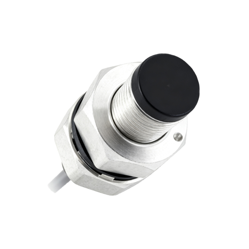
External conditions impose practical constraints on response time. The target material, size, and approach speed directly impact the detection event. For inductive sensors, different metals (steel, aluminum, copper) affect the damping of the oscillator at different rates. The sensing distance also matters; operating a sensor at its maximum nominal range might reduce its response speed compared to using it at a closer, recommended distance. Environmental factors like extreme temperatures, electrical noise, or contamination can also degrade performance and increase effective response time.
Measuring response time accurately requires an oscilloscope, a standardized test target, and a controlled setup. The target is moved toward and away from the sensor at a defined speed. The oscilloscope probes are connected to monitor both the target position trigger and the sensor's output signal. The time lag between these two signals is the measured response time. It is vital to consult the manufacturer's datasheet, as specifications often define response time under specific, ideal conditions (e.g., a standard target, rated voltage, 25°C ambient temperature).

To optimize system performance around sensor response time, engineers must adopt a holistic approach. The primary step is correct sensor selection. Choose a sensor technology and model whose specified maximum response time is significantly faster than the required cycle time of the application. For high-speed counting or sorting, sub-millisecond inductive sensors are preferred. Consider sensors with specialized fast-response circuitry or "Speed Boost" functions some manufacturers offer.
Installation and wiring are critical. Minimizing the distance between the sensor and the controller (PLC) reduces signal transmission delay. Using shielded cables and proper grounding mitigates electrical noise that can cause signal instability and delay. Ensuring a stable, regulated power supply prevents voltage dips that could affect internal circuitry speed. Regular maintenance, including cleaning the sensing face and checking for mechanical wear, preserves optimal performance.
Furthermore, system programming can compensate for sensor limitations. Using hardware interrupts on the PLC input card for critical high-speed signals can provide faster processing than standard cyclic scanning. Implementing filtering or debounce logic in software must be done judiciously, as excessive filtering intentionally adds delay to stabilize signals but will increase the effective system response time.
In conclusion, proximity sensor response time is not a singular, fixed value but a performance characteristic shaped by an interplay of technology, design, and application environment. A deep understanding of these factors empowers engineers to make informed selections, implement robust installations, and ultimately design automated systems that achieve peak speed, precision, and reliability. Ignoring response time specifications can lead to missed counts, production bottlenecks, or even machine malfunctions, underscoring its importance in successful system integration.