In the realm of industrial automation and control systems, proximity sensors are indispensable components for detecting the presence or absence of objects without physical contact. Their reliability and accuracy are paramount, and a critical factor influencing their performance is the installation process, specifically the threaded mounting. Improper installation can lead to premature sensor failure, inaccurate readings, physical damage, and costly downtime. This guide details the essential threaded installation specifications and best practices for electrical engineers and technicians to ensure optimal sensor functionality and longevity.
The foundation of a proper installation begins long before the wrench is turned. It starts with selecting the correct sensor body style and thread specification for the application. Proximity sensors commonly feature standardized metric (M) or imperial (NPT) threads. Metric threads, such as M8, M12, M18, and M30, are prevalent globally and are defined by their nominal diameter and pitch (e.g., M12x1.0). National Pipe Taper (NPT) threads are tapered and commonly used in North America, creating a seal through thread deformation. It is crucial to verify the thread specification on the sensor datasheet and ensure the mounting hole in the machine frame or bracket is tapped to the matching specification. Using an incorrect tap or forcing a mismatched thread will compromise the mechanical integrity.
Preparation of the mounting location is the next critical step. The mounting surface must be clean, flat, and free of burrs, paint, or debris. Any irregularities can cause the sensor to sit at an angle, affecting its sensing field and potentially damaging the threads. For through-hole mounting, deburr both the entry and exit points of the hole. If installing into a blind hole, ensure the hole depth is sufficient to accommodate the entire threaded portion of the sensor without the sensing face bottoming out. The hole should be deep enough to allow the sensor to be fully seated, typically with one to two threads protruding, depending on the use of a locking nut.
The installation procedure itself requires care and the correct tools. Avoid using pipe wrenches or adjustable wrenches that can mar the sensor housing. Instead, use a properly sized open-end wrench or a socket that fits the sensor's hex flats. For cylindrical body sensors without hex flats, a dedicated sensor mounting tool or a deep-well socket is recommended. When threading the sensor, start by hand to prevent cross-threading. Cross-threading is a primary cause of damage and occurs when the threads are misaligned during initial engagement. If resistance is felt immediately, back the sensor out and restart the alignment.
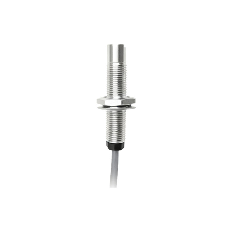
For straight metric threads, hand-tighten until the sensor is flush or as specified, then use a wrench to apply final torque. Torque specification is non-negotiable. Overtightening can crack the sensor housing, strip the threads, or distort internal components, while under-tightening can lead to loosening from vibration. Consult the manufacturer's datasheet for the exact torque value. As a general reference, for common plastic-bodied M12 sensors, torque is typically around 10-15 Nm, while metal-bodied M18 sensors may withstand 20-30 Nm. Always adhere to the provided specifications.
For tapered NPT threads, the process differs. Apply a small amount of appropriate sealant (e.g., PTFE tape or liquid thread sealant) to the male threads of the sensor, leaving the first two threads bare to prevent contamination of the sensing face. Hand-tighten, then use a wrench to turn the sensor further—usually specified as a number of turns past hand-tight (e.g., 2-3 turns). The goal is to achieve a pressure-tight seal through thread interference without over-stressing the housing.
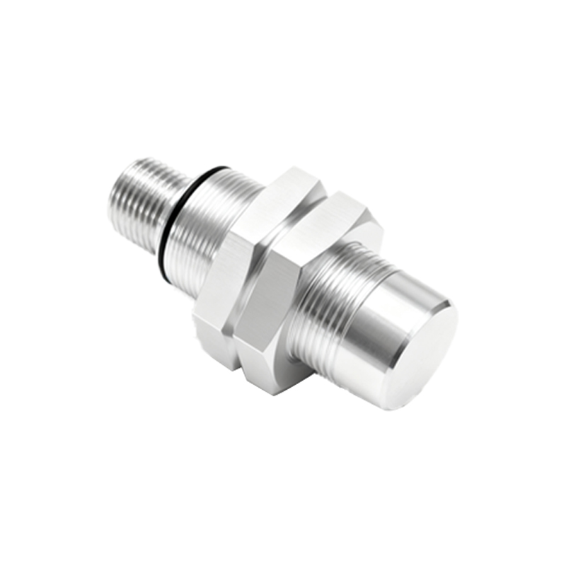
In applications with high vibration, additional securing methods are essential. After proper torquing, use a locknut on the backside of the mounting surface if the sensor design allows. Alternatively, thread-locking adhesives (e.g., Loctite) can be applied to the threads. However, ensure the adhesive is compatible with the sensor housing material and the application environment, and be aware that it may make future removal difficult.
Finally, consider the sensing face orientation and clearance. The active sensing face must have a clear, unobstructed field of view to the target. Maintain the specified mounting flush or non-flush distance from the target. After installation, perform a functional test. Power the sensor and use the target object to verify the switching response is consistent and at the expected distance. Monitor the sensor indicator LED (if present) for correct operation.
Adherence to these threaded installation specifications is not merely procedural; it is a direct investment in system reliability. By meticulously selecting, preparing, and installing proximity sensors with the correct torque and technique, engineers can prevent a significant majority of field failures, ensuring robust and uninterrupted operation in demanding industrial environments.

SEO