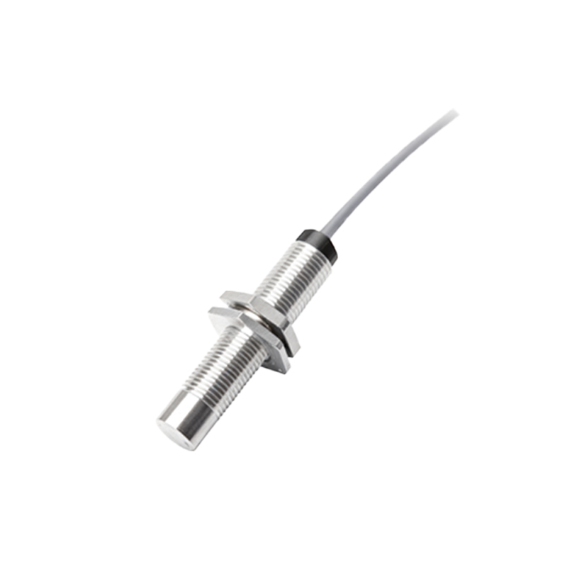
Inductive proximity sensors are fundamental components in industrial automation, offering non-contact detection of metallic objects. Their operation relies on electromagnetic induction, where an oscillator generates a high-frequency electromagnetic field from a coil wound around a ferrite core. When a metallic target enters this field, eddy currents are induced on the target's surface, causing a change in the sensor's oscillation amplitude. This amplitude change is then processed by an evaluation circuit to produce a clean, binary output signal—typically switching from a high to low state (or vice versa, depending on the sensor's configuration).
The integrity and reliability of this output signal are paramount for system performance. Key signal characteristics include switching frequency, hysteresis, and repeat accuracy. Switching frequency, measured in Hertz (Hz), defines how quickly a sensor can detect objects per second. For instance, a sensor with a 1 kHz switching frequency can theoretically detect up to 1000 targets per second, making it suitable for high-speed counting or sorting applications. Hysteresis is a built-in feature that prevents output signal chatter when a target is near the switching point. It creates a small difference between the switch-on point (when the target approaches) and the switch-off point (when the target recedes), ensuring stable operation even in the presence of mechanical vibration or minor target position variations. Repeat accuracy refers to the sensor's ability to consistently trigger at the same distance from the target under stable environmental conditions, often specified in micrometers or millimeters.
Environmental factors significantly influence signal stability. Temperature fluctuations can affect the oscillator's frequency and the damping characteristics, potentially altering the sensing distance. Modern sensors incorporate temperature compensation circuits to mitigate this drift. Electrical noise from nearby motors, frequency converters, or welding equipment can induce interference, leading to false triggering. Proper installation practices are crucial: using shielded cables, ensuring secure grounding, and maintaining adequate separation from noise sources. Additionally, the target material's properties—specifically its electrical conductivity and magnetic permeability—directly impact sensing performance. Ferrous metals (like mild steel) generate a stronger eddy current response and are detected at greater standard sensing distances compared to non-ferrous metals (such as aluminum or copper). For non-ferrous or thin targets, sensors with extended range or factor-1 capability (where the sensing distance for steel is approximately equal to that for aluminum) are often employed.
Output configurations also define the signal interface. Two-wire DC sensors are wired in series with the load, simplifying installation but requiring a minimum current (leakage current) to maintain operation, which can sometimes cause a residual voltage drop. Three-wire DC sensors provide separate power, ground, and switched output wires, offering either NPN (sinking) or PNP (sourcing) transistor outputs. This configuration allows for near-zero leakage current and is compatible with most programmable logic controllers (PLCs). Four-wire DC sensors combine both an NPN and a PNP output in one housing, providing flexibility for controlling different load types. Analog output versions (e.g., 4-20 mA or 0-10 V) provide a continuous signal proportional to the target distance, enabling applications like position monitoring or thickness measurement, rather than simple presence detection.
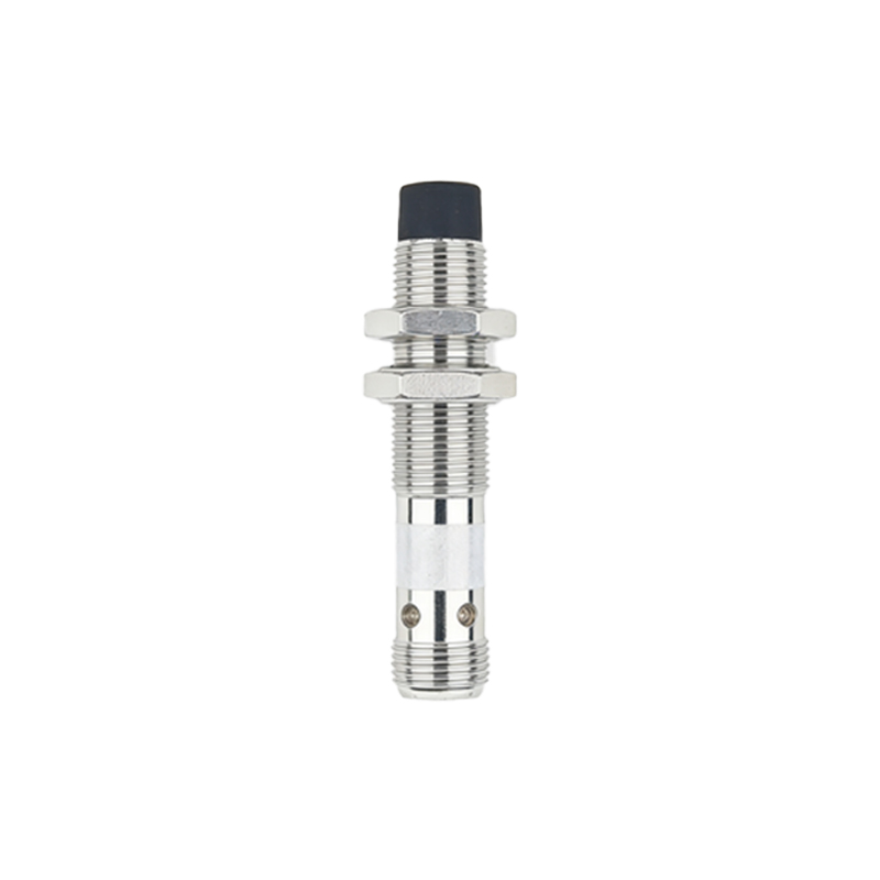
For optimal signal integrity, correct sensor selection and installation are critical. The mounting style (flush or non-flush) affects the sensing field geometry and the effective sensing distance. Non-flush mountable sensors offer longer ranges but require lateral clearance from metallic surroundings to avoid shielding effects. Flush-mounted sensors can be embedded in metal without influence from adjacent material but have reduced sensing ranges. The installation environment must be considered: sensors rated for IP67 or higher are protected against dust and temporary immersion, suitable for harsh washdown areas. Regular maintenance checks should verify the absence of metal debris accumulation on the active face, which can cause permanent activation, and inspect cable integrity for any damage that could compromise signal transmission.
In summary, the signal from an inductive proximity sensor is a robust, digitally switched output derived from precise electromagnetic principles. Understanding its generation, key parameters like switching frequency and hysteresis, and the influences of target material, electrical noise, and environmental conditions allows engineers to deploy these sensors reliably in demanding automation systems, from packaging machinery and robotic cells to automotive assembly lines.