In industrial automation and control systems, normally closed (NC) proximity sensors are fundamental components, reliably detecting the presence or absence of objects without physical contact. A sudden failure where the sensor's indicator light does not illuminate can bring a production line to an abrupt halt, leading to costly downtime. This guide provides a systematic, engineer-level approach to diagnosing and resolving this common issue, focusing on inductive-type NC proximity sensors, which are prevalent in metal detection applications.
The first and most critical step is to ensure absolute safety. Lock out and tag out (LOTO) the associated electrical circuit before performing any inspection or testing. Verify that the machine or process is in a safe state and cannot be accidentally energized.
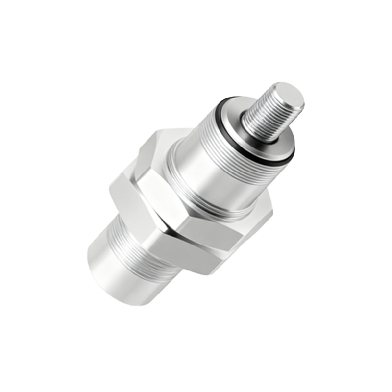
Begin the diagnostic process with a thorough visual inspection. Examine the sensor's housing for any signs of physical damage, such as cracks, dents, or impact marks. Check the cable and its entry point into the sensor for cuts, abrasions, or pinch points. Environmental factors are a common culprit; look for accumulations of metal chips, dust, oil, or coolant that could be coating the sensing face or interfering with operation. Ensure the sensor is securely mounted and that its position relative to the target has not shifted due to vibration.
Next, verify the power supply. A non-illuminating LED often points directly to a power issue. Using a calibrated multimeter, measure the voltage between the supply (typically +V, brown wire) and common (0V, blue wire) at the sensor's connector or terminal block. Compare this reading to the sensor's specified voltage range (e.g., 10-30V DC). A reading of zero indicates a blown fuse, a tripped circuit breaker, or a faulty power supply module upstream. A voltage significantly outside the specified range can prevent the sensor from operating correctly. Don't assume the power is good; always measure.
If power is confirmed, the focus shifts to the wiring and load circuit. For a 3-wire DC NC sensor, the black wire is the signal output. In its normal state (no target present), this NC output should be electrically "closed," connecting the load (like a PLC input) to the common (blue wire). Use your multimeter to check for continuity between the black (output) and blue (common) wires with the target removed. You should measure very low resistance. If you measure an open circuit (infinite resistance), the sensor's internal switching element may have failed. Also, check the wiring to the load. A short circuit in the load wiring or within the PLC input module itself can cause excessive current draw, potentially damaging the sensor's output transistor and causing the LED to remain off. Temporarily disconnect the sensor's output wire from the load and see if the indicator light turns on. If it does, the fault lies in the load circuit or wiring.
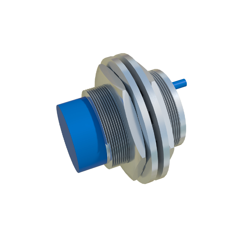
Another vital check is the load itself. Ensure the load (e.g., the PLC input, relay coil) is functional and its impedance is within the sensor's rated specifications. An overload condition can permanently damage the output stage. Also, verify the sensor's sink/source (NPN/PNP) configuration matches the control system's requirements. Connecting an NPN (sinking) sensor to a sinking input, for instance, will not work.
Don't overlook the target. The problem might not be the sensor but the object it is meant to detect. Confirm the target material is ferrous or non-ferrous metal (for inductive sensors) and that it is within the sensor's rated sensing distance. Test with a standard target, like a piece of mild steel, to rule out target-related issues. Also, check for the presence of other metals in the sensing field that could be causing electromagnetic interference or creating a false "target present" condition that keeps the output open.
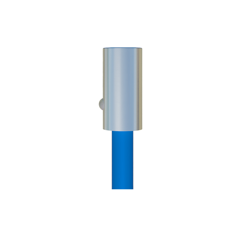
If all external factors—power, wiring, load, and target—are verified and correct, the conclusion points to an internal sensor failure. The internal oscillator, amplifier, or output switching circuit may be damaged due to voltage spikes, excessive current, or prolonged exposure to harsh conditions beyond its IP rating. Proximity sensors have a finite lifespan, and failure can occur.
As a final verification before replacement, consult the sensor's datasheet. Some models have a built-in diagnostic function or a specific LED flash pattern indicating certain faults. Also, if possible, swap the suspect sensor with a known-good unit of the same model from a non-critical area. If the good sensor works and the problem follows the original sensor, replacement is necessary.
In summary, a methodical approach is key: Safety First, Visual Inspection, Power Verification, Wiring & Load Check, Target Assessment, and finally, Sensor Replacement. Keeping a log of such failures can help identify patterns, such as repeated failures in a specific area pointing to environmental or electrical noise issues, leading to