Proximity sensors are indispensable components in modern industrial automation, robotics, and safety systems. Their ability to detect the presence or absence of an object without physical contact makes them reliable and long-lasting. This article delves into the core circuit design principles for inductive and capacitive proximity sensors, providing a practical guide for electrical engineers.
Fundamental Operating Principles
At its heart, a proximity sensor circuit generates an electromagnetic or electrostatic field. The detection of a target object causes a measurable change in this field. For inductive sensors, the target must be a conductive metal. The sensor's core is an LC oscillator circuit, where 'L' is a coil (the sensing element) and 'C' is a capacitor. When a metallic object enters the oscillating magnetic field, eddy currents are induced in the object. This energy loss increases the oscillation damping, effectively reducing the amplitude of the oscillation. A subsequent threshold detection circuit monitors this amplitude drop.
Capacitive sensors, on the other hand, can detect both metallic and non-metallic materials (plastics, wood, liquids). They operate by generating an electrostatic field between two electrodes (often the sensor face and a ground plane). When any object with a different dielectric constant enters this field, it alters the capacitance of the system. This change in capacitance is typically measured by incorporating it into an RC or LC oscillator circuit, changing its frequency. A frequency-to-voltage converter or a comparator circuit then triggers the output.
Core Circuit Design Blocks
A robust proximity sensor circuit comprises several key stages:
1. Oscillator Stage: This is the signal source. For inductive types, a Colpitts or Hartley oscillator using the sensing coil in the tank circuit is common. For capacitive types, a 555 timer in astable mode or a dedicated capacitance-to-digital converter IC provides flexibility. Stability and noise immunity are critical design considerations here.
2. Demodulation/Detection Stage: The modulated signal from the oscillator needs to be converted into a DC voltage proportional to the change. For amplitude-based inductive sensors, a peak detector or an envelope detector circuit (using a diode, resistor, and capacitor) is standard. For frequency-based capacitive sensors, a phase-locked loop (PLL) or a simple frequency-to-voltage converter (like the LM2917 IC) can be employed.
3. Threshold Comparator Stage: The DC signal is fed into a comparator (e.g., using an LM393). A reference voltage, set by a potentiometer to define the sensing range, is applied to the comparator's other input. When the signal voltage crosses the reference threshold (indicating target presence), the comparator's output state switches (e.g., from HIGH to LOW). Hysteresis (using positive feedback) must be added to this stage to prevent output chatter when the target is at the borderline of the detection range.
4. Output Stage: This interfaces with the control system. Common outputs include:
NPN/PNP Transistor (Sinking/Sourcing): The most prevalent in industrial DC sensors. An NPN output sinks current to common, while a PNP sources current from the positive supply.
Analog Output (0-10V or 4-20mA): Provides a continuous signal proportional to the distance to the target, useful for positioning applications.
Solid-State Relay (SSR): For switching AC loads directly.
5. Power Supply & Protection: A regulated internal power supply (often 12-24V DC) is required. Essential protection circuits include reverse polarity protection (using a diode), voltage transient suppression (TVS diodes), and output short-circuit protection (current limiting resistors or dedicated ICs).
Design Considerations and Best Practices
Noise Immunity: Industrial environments are electrically noisy. Shielding the sensing coil/capacitor, using twisted-pair cables for signals, incorporating low-pass filters in the signal path, and employing a clean, regulated power supply are non-negotiable.
Temperature Stability: Component values drift with temperature. Selecting components with low temperature coefficients (e.g., NPO/COG capacitors) and designing for a wide operating temperature range (-25°C to 70°C typical) is crucial.
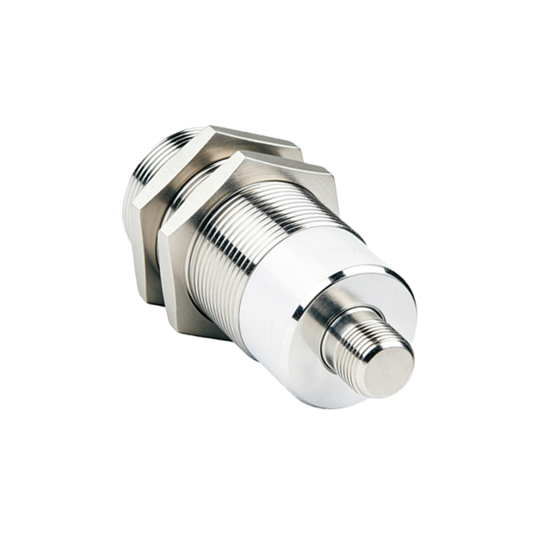
Housing and Sensing Face: The material of the sensor housing (typically PBT or stainless steel) and the type of sensing face (flush or non-flush mount) significantly affect the sensing field and range. Non-flush mount sensors offer longer ranges but require more clearance around them.
Testing and Calibration: Prototypes must be tested with various target materials, sizes, and under different environmental conditions (temperature, humidity). Calibration involves precisely setting the threshold potentiometer or programming the detection algorithm in a microcontroller-based design.
Advanced Integration: Microcontroller