Proximity sensors are indispensable components in modern automation, manufacturing, and consumer electronics. They detect the presence or absence of an object within a specific range without physical contact. However, their effectiveness hinges on proper adjustment and calibration. Incorrect settings can lead to false triggers, missed detections, or erratic system behavior. This guide provides a comprehensive, step-by-step approach to adjusting various types of proximity sensors for reliable operation.
Before beginning any adjustment, safety is paramount. Always disconnect power to the machine or system where the sensor is installed. Consult the manufacturer's datasheet for your specific sensor model. This document contains critical information such as sensing range, electrical specifications, output type (PNP/NPN, NO/NC), and adjustment procedures.
The first step is mechanical mounting and alignment. Ensure the sensor is securely fastened in its bracket. The sensing face must be correctly oriented toward the target object. For inductive sensors (detecting metals), the sensing face should be parallel to the target surface. For capacitive sensors (detecting various materials, including liquids and plastics), ensure no interfering objects are near the sensing field. Photoelectric sensors require a clear line of sight between the emitter and receiver or the target.
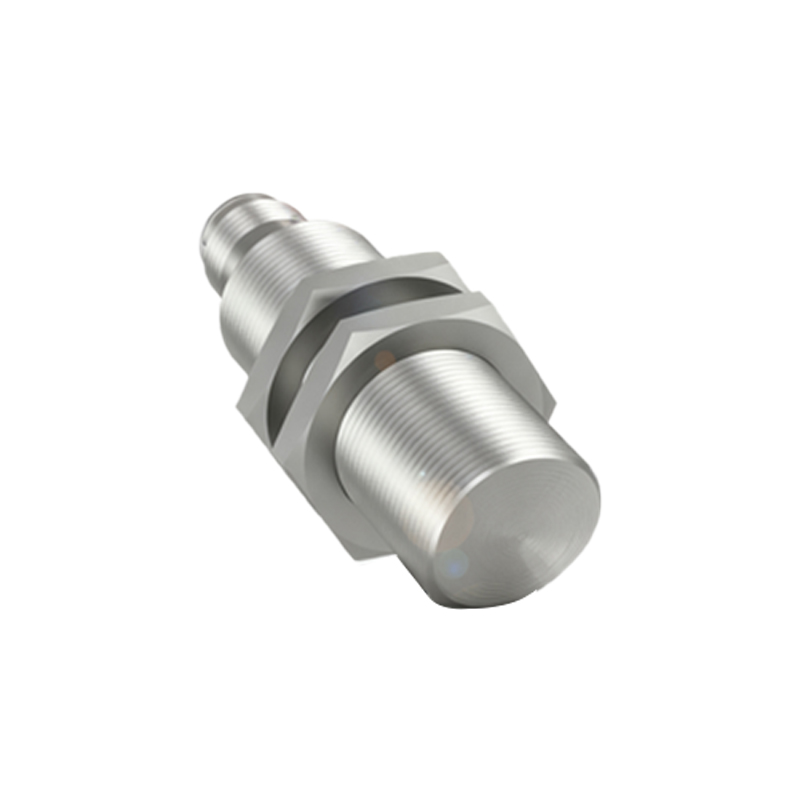
Once mounted, power the system. Most proximity sensors have a built-in indicator light, typically an LED. This light is your primary tool for adjustment. It usually illuminates or changes color when the sensor detects an object within its effective range.
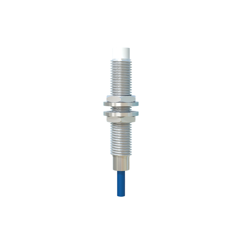
The core adjustment involves setting the sensing distance or sensitivity. Many sensors feature a potentiometer (a small screw) for this purpose. For a standard adjustable sensor, follow this process:
1. Place the standard target object (as specified in the datasheet, e.g., a square steel plate of defined size) at the nominal sensing distance.
2. Using a non-conductive adjustment tool, slowly turn the potentiometer clockwise (usually to increase sensitivity) until the indicator light just turns on, signaling detection.
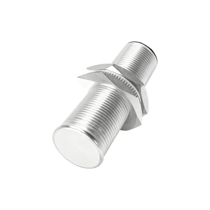
3. Then, slowly turn the potentiometer counterclockwise until the indicator light just turns off.
4. Finally, turn the potentiometer back clockwise to a point midway between the "on" and "off" points. This midpoint provides the most stable operating point, offering a buffer against environmental variations like voltage fluctuations or temperature changes.
For sensors with a teach-in function, the process is more automated. This method is common in ultrasonic and some advanced photoelectric sensors. Typically, you press and hold a button on the sensor, present the target at the desired maximum detection distance, and release the button. The sensor learns this distance as its new reference point. Some models allow you to set both near and far limits.
Hysteresis is a crucial concept. It is the difference between the switch-on point and the switch-off point. Adequate hysteresis prevents rapid, chattering on/off signals if the target is hovering at the exact detection threshold. The midpoint adjustment method described above inherently accounts for the sensor's designed hysteresis. Do not attempt to eliminate it.
Environmental factors significantly impact performance. For inductive sensors, consider the target material's properties. Stainless steel has a lower detection range than mild steel. Always test with the actual target material. For capacitive sensors, humidity, dust, or contamination on the sensing face can cause drift. Clean the face regularly and adjust sensitivity in the actual operating environment to compensate. Photoelectric sensors are susceptible to ambient light interference. Use sensors with modulated light sources and install shades or housings if necessary. Ultrasonic sensors can be affected by air turbulence, temperature, and soft, sound-absorbing materials.
After adjustment, rigorous testing is mandatory. Do not test with your hand for inductive or capacitive sensors, as the detection characteristics differ. Use the actual target object. Move the target repeatedly into and out of the sensing field at the required speed. Verify the sensor triggers consistently and the output signal is clean. Test under various conditions, such as at the extremes of the operating temperature range or with different supply voltages, if applicable.
Finally, document your settings. Note the position of the potentiometer or the taught distance. This practice aids in future maintenance or troubleshooting.
Regular maintenance checks are recommended. Vibration can loosen mounts, and environmental buildup can degrade performance over time. A periodic check of the indicator light's operation against a known target can preempt system failures.
By following these systematic steps—understanding your sensor, ensuring proper mounting, carefully adjusting sensitivity while considering hysteresis, accounting for environmental factors, and conducting thorough testing—you can ensure your proximity sensors operate with maximum reliability and longevity, forming a robust foundation for your automated systems.