Proximity sensors are fundamental components in modern industrial automation, robotics, and countless electronic systems. At their core, these devices detect the presence or absence of an object within a specified range without physical contact. The underlying circuit is what transforms a simple sensing principle into a reliable, actionable signal. This article delves into the essential circuitry of common proximity sensor types, explaining their operation from an electrical engineering perspective.
The most prevalent categories are inductive, capacitive, and photoelectric sensors. Each employs a distinct sensing method and, consequently, a unique circuit architecture.
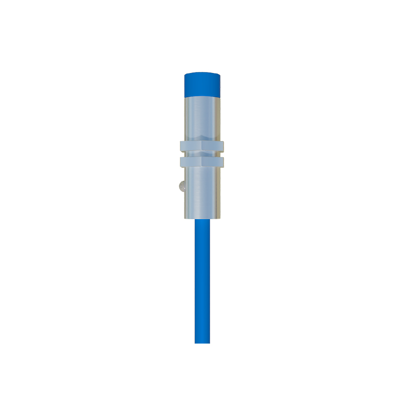
Inductive Proximity Sensor Circuits
Inductive sensors detect metallic objects. The heart of the circuit is an oscillator coil (L) and a capacitor (C) forming a resonant LC tank circuit, typically operating in the range of 100 kHz to 1 MHz. An oscillator circuit, often built around a dedicated IC or transistor configuration, drives this tank, maintaining sustained oscillations. When a ferrous or non-ferrous metal object enters the sensor's electromagnetic field, eddy currents are induced in the target. This causes a load on the oscillator, damping or stopping the oscillations. A subsequent signal conditioning stage, comprising an amplitude detector (like a diode and capacitor for peak detection) and a Schmitt trigger, converts this change in oscillation amplitude into a clean, sharp digital output signal (e.g., PNP or NPN transistor switch). The output stage is crucial for interfacing with Programmable Logic Controllers (PLCs) or other control systems, providing the necessary current sinking or sourcing capability.
Capacitive Proximity Sensor Circuits
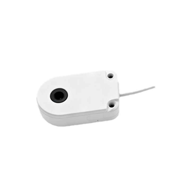
Capacitive sensors can detect both metallic and non-metallic materials (plastics, wood, liquids) by sensing changes in capacitance. The circuit centers around a capacitor formed by the sensor's active face (one plate) and the ground (the other plate). An object entering the field alters the dielectric constant, changing the capacitance. This sensor often uses an RC or relaxation oscillator circuit. The changing capacitance modifies the oscillation frequency or the time constant of the circuit. A frequency-to-voltage converter or a comparator circuit then monitors this shift. When the change exceeds a pre-set threshold—adjustable via a potentiometer for sensitivity calibration—the comparator toggles the output state. These circuits require careful shielding and grounding to minimize false triggers from environmental humidity or contamination.
Photoelectric Sensor Circuits
Photoelectric sensors use light beams (visible, infrared, or laser). The circuit is divided into the emitter and receiver sections. The emitter circuit drives a light-emitting diode (LED) or laser diode with a constant or pulsed current, often modulated at a specific frequency to enhance noise immunity against ambient light. The receiver side houses a phototransistor, photodiode, or in some cases, a CMOS/CCD array. The received light signal generates a small photocurrent. This微弱 current is fed into a high-gain transimpedance amplifier to convert it into a usable voltage. Following this, a demodulator circuit (synchronized with the emitter's modulation) filters out the DC component from ambient light and extracts only the modulated signal. Finally, a comparator determines if the signal strength is above (for diffuse or retro-reflective modes) or below (for through-beam mode) a threshold, triggering the solid-state output.
Common Circuit Elements and Design Considerations
Beyond the sensing-specific blocks, several universal elements are critical. A robust power supply section with reverse polarity protection, voltage regulation, and filtering is mandatory for stable operation in electrically noisy industrial environments. Short-circuit and overload protection on the output stage is a standard safety feature. Many modern sensors incorporate microcontrollers for advanced functions like programmable sensing windows, time delays, and diagnostic LED indicators communicating operating status (power, output active, fault conditions).
Designing or selecting a proximity sensor circuit requires careful consideration of several parameters: sensing distance (rated and effective), hysteresis (the difference between the switch-on and switch-off points to prevent chatter), response frequency, output type (digital NPN/PNP, analog 4-20mA, IO-Link), and environmental ratings (IP67, NEMA). Electrical noise immunity, achieved through proper circuit layout, shielding, and modulation techniques, is paramount for reliability.
In summary, the circuit of a proximity sensor is a sophisticated integration of oscillators, amplifiers, signal conditioners, and output drivers tailored to a specific physical sensing principle. Understanding these circuits enables engineers to optimally select, integrate, and troubleshoot these vital components, ensuring robust performance in automated systems. The trend continues toward smarter, more integrated circuits with digital communication buses, embedding greater intelligence directly at the sensor point.