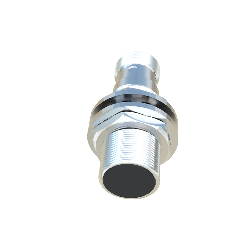
In the realm of industrial automation and machine safety, the proximity sensor stands as a fundamental component. Its conceptual design is not merely a drawing but a blueprint that dictates functionality, reliability, and integration. This article delves into the core elements of a proximity sensor conceptual design diagram, elucidating the principles and considerations that underpin its creation for electrical engineering professionals.
At its heart, a proximity sensor is a non-contact device that detects the presence or absence of an object within its sensing range. The conceptual design diagram serves as the primary visual and technical document that translates this operational principle into a tangible engineering plan. It typically begins with the core sensing technology block. This is the nucleus of the diagram, clearly labeled to indicate whether the design employs inductive, capacitive, ultrasonic, or photoelectric principles. For instance, an inductive sensor core would be depicted with an oscillator coil and associated circuitry, highlighting its exclusive use for detecting metallic targets. Adjacent to this, the signal conditioning and processing unit is illustrated. This block represents the electronic brain that converts the raw, often analog, signal from the sensing element into a clean, digital output signal. It includes components for amplification, filtering, and comparison against a preset threshold. The design must detail the transition from a fluctuating detection field to a definitive HIGH/LOW logic state.
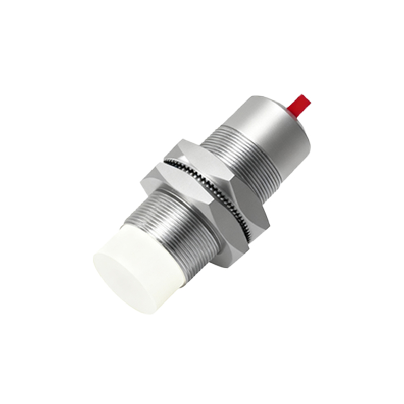
The output stage is another critical element prominently featured. The diagram must specify the output type: a PNP (sourcing) or NPN (sinking) transistor configuration, a relay contact, or an analog (4-20mA or 0-10V) output. This section connects the sensor's internal logic to the external control system, such as a Programmable Logic Controller (PLC). Wiring and connection points are meticulously shown, often with standardized terminal designations (e.g., +V, Output, 0V). Furthermore, a well-crafted conceptual diagram includes the physical and environmental interface. This involves the housing design, material specifications (e.g., stainless steel for harsh environments), and the sensing face geometry. It may show protective elements like LED status indicators for diagnostics and sealing details (IP67, IP69K ratings) to denote ingress protection against dust and water.
A crucial, yet sometimes overlooked, part of the diagram is the field representation. For inductive and capacitive sensors, the diagram often includes a depiction of the electromagnetic or electrostatic field around the active face, usually shown as concentric lines or a lobe shape. This visually defines the nominal sensing distance (Sn) and the effective operational range, emphasizing the non-contact nature. The concept of hysteresis is also integrated graphically or via notation, showing the differential between the switch-on and switch-off points to prevent output chatter. For designs involving adjustable sensing ranges or sensitivity, the diagram incorporates potentiometer symbols or digital interface points for configuration.
Power supply requirements are explicitly defined, showing the acceptable voltage range (e.g., 10-30V DC) and current consumption. Protection circuitry against reverse polarity, short-circuit, and overload conditions is also symbolized, ensuring design robustness. In advanced conceptual designs for IO-Link or AS-Interface sensors, a dedicated communication protocol block is added, detailing the data exchange parameters with the master controller. The ultimate goal of this comprehensive diagram is to provide a holistic view that balances electrical characteristics, mechanical constraints, and application-specific performance metrics. It acts as the foundational document guiding subsequent stages of schematic design, PCB layout, firmware development, and housing fabrication. By meticulously planning each interface and function block in the conceptual phase, engineers can preempt integration challenges, optimize performance for target applications (such as high-speed counting or precise position detection), and ensure the final product meets stringent industry standards for safety, reliability, and efficiency.