Proximity switch sensors are indispensable components in modern industrial automation, offering non-contact detection of metallic or non-metallic objects. Understanding the correct wiring of the sensing point is crucial for ensuring reliable operation, safety, and system longevity. This guide provides a comprehensive overview of proximity sensor wiring diagrams, focusing on the sensing point connections, common configurations, and best practices for installation.
Proximity sensors typically operate on the principle of electromagnetic induction, capacitive sensing, or ultrasonic technology. The sensing point, often the front face or a specified area of the sensor, is where the detection occurs. Wiring this point correctly involves connecting the sensor to a power supply and a load, such as a programmable logic controller (PLC), relay, or indicator. Most industrial proximity sensors have three or four wires, color-coded for ease of identification: brown for positive voltage supply, blue for negative or common, black for output signal, and sometimes white for a second output or diagnostic function.
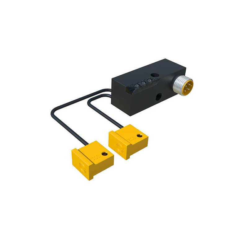
The wiring diagram varies based on the sensor type—sinking (NPN) or sourcing (PNP). In a sinking configuration, the output wire connects to the load, which is then linked to the positive voltage. When the sensor detects an object, it switches the output to ground, completing the circuit. Conversely, in a sourcing setup, the output provides positive voltage to the load upon detection. It is essential to match the sensor type with the control system's requirements to avoid malfunctions. For instance, PLCs often specify whether they accept sinking or sourcing inputs.
When wiring the sensing point, always refer to the manufacturer's datasheet for precise diagrams and specifications. Key steps include: ensuring power is disconnected during installation, using shielded cables to reduce electromagnetic interference, and maintaining proper cable lengths to prevent signal degradation. The sensing point should be positioned to avoid physical damage from moving parts and environmental factors like moisture, dust, or extreme temperatures. Additionally, consider the sensing distance—maintain a gap between the sensor and target object as per technical guidelines to prevent false triggers.
Common issues in wiring include reverse polarity, loose connections, or incorrect voltage supply, leading to sensor failure or erratic behavior. Testing with a multimeter can verify continuity and output signals. For complex systems, integrating multiple sensors may require careful planning to avoid cross-talk or interference. Always follow industry standards, such as IEC 60947-5-2, for safety and compatibility.
In summary, proper wiring of the proximity switch sensor sensing point is foundational to automation efficiency. By adhering to wiring diagrams, selecting appropriate sensor types, and implementing robust installation practices, engineers can optimize performance and minimize downtime in industrial applications. Regular maintenance and calibration further ensure long-term reliability, making proximity sensors a trusted solution for object detection across various sectors, from manufacturing to robotics.