In the realm of industrial automation, proximity sensors serve as the fundamental eyes of a control system, detecting the presence or absence of objects without physical contact. A critical, yet sometimes overlooked, aspect of their reliable operation is the signal line voltage. This voltage is not merely a power supply parameter; it is the lifeblood of the sensor's communication with the programmable logic controller (PLC) or other control units. This article delves into the intricacies of proximity sensor signal line voltages, exploring their role, standard ranges, and practical considerations for system design and troubleshooting.
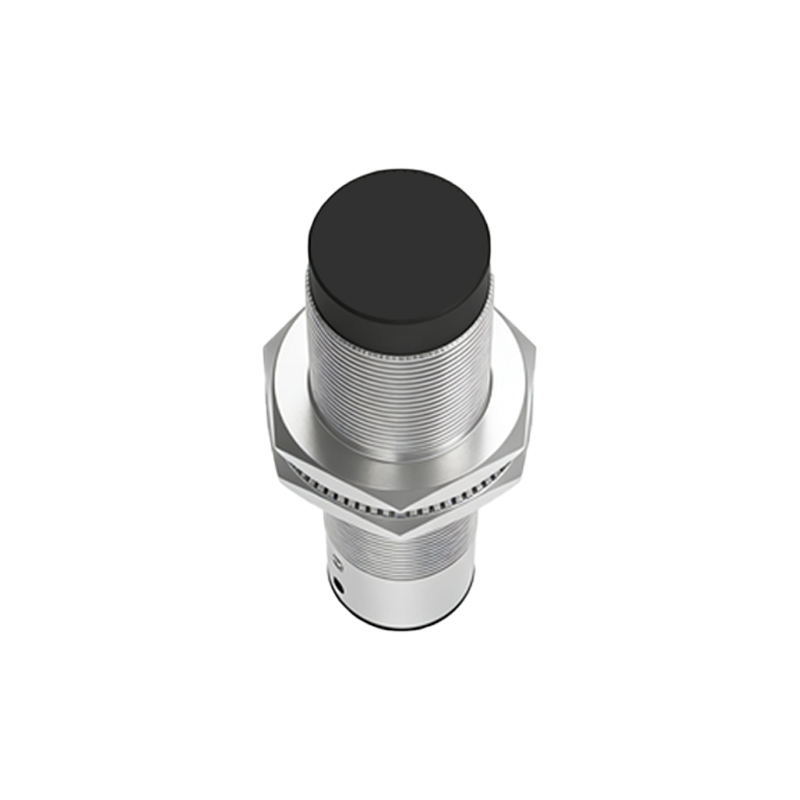
Proximity sensors, whether inductive, capacitive, or photoelectric, fundamentally operate by generating a sensing field. When a target interrupts or influences this field, the sensor's internal circuitry triggers a change in the state of its output switch. This output switch is connected to the signal line. The voltage present on this line, therefore, represents the sensor's binary message: "target present" or "target absent." For a standard 3-wire DC sensor, the wiring typically comprises a brown wire for DC positive supply (e.g., +24V DC), a blue wire for DC common (0V), and a black wire as the signal output line.
The voltage on this black signal line is what the PLC input module reads. In a sinking (NPN) configuration, the sensor's output switch connects the signal line to the common (0V) when active. Thus, an active state is represented by a voltage close to 0V (low signal), while an inactive state leaves the signal line floating or pulled high, often to the supply voltage through an external or internal pull-up resistor. Conversely, in a sourcing (PNP) configuration, the output switch connects the signal line to the positive supply when active. Here, an active state presents a voltage near the supply level (e.g., +24V, a high signal) to the PLC, while an inactive state pulls it low.
Standard industrial DC supply voltages are predominantly 10-30V DC, with 24V DC being the de facto global standard. Consequently, the signal line voltage in its active state will approximate either 0V or 24V, depending on the sensor's output type (NPN or PNP) and the integrity of the circuit. It is crucial to match the sensor's output type with the PLC input type. A PNP sensor (sourcing) requires a sinking PLC input, and an NPN sensor (sinking) requires a sourcing PLC input. Mismatching these can lead to a complete failure of signal detection or potential damage.
However, the real-world signal voltage is seldom a perfect 0V or 24V. Voltage drops occur due to wire resistance, connector contact resistance, and internal semiconductor voltage drops within the sensor and PLC. A high-quality system might see an active PNP signal at 23.5V or an active NPN signal at 0.5V, which are still well within the recognized thresholds for "ON" and "OFF" states defined by PLC input modules. These modules have a guaranteed "ON" voltage range (e.g., 15V or above for a 24V system) and a guaranteed "OFF" voltage range (e.g., 5V or below). The region between is an indeterminate zone to be avoided.
Several factors can cause abnormal signal line voltages, leading to erratic machine behavior. Excessive cable length with insufficient wire gauge can cause a significant voltage drop, potentially pushing a "high" signal into the indeterminate zone. Electrical noise from variable frequency drives (VFDs), welding equipment, or large motors can induce alternating currents on the signal line, which may be misinterpreted by the PLC. Using shielded cables, proper grounding at one end only, and routing signal lines away from power cables are essential mitigation strategies. Another common issue is leakage current, particularly in capacitive sensors or faulty devices, where a small current flows through the output transistor even in the "OFF" state. This current, passing through the PLC's internal impedance, can create a phantom voltage high enough to falsely trigger a sinking input. The solution often involves installing a bleed-down resistor across the PLC input to dissipate this leakage current.
When troubleshooting, a digital multimeter (DMM) is the primary tool. Measuring the voltage between the sensor's signal wire (black) and the blue common wire under active and inactive conditions provides immediate insight. An oscilloscope is invaluable for diagnosing noise-related issues, revealing AC ripple superimposed on the DC signal. Always refer to the sensor and PLC datasheets for specific voltage specifications, output types, and leakage current values.
In conclusion, the proximity sensor signal line voltage is a simple DC level that carries profound operational significance. A deep understanding of its expected values based on output configuration, awareness of factors that can corrupt it, and proficiency in measuring it are indispensable skills