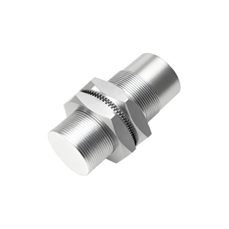
In the realm of industrial automation and machine safety, the proximity switch sensor stands as a fundamental component. Its design, often encapsulated within a detailed schematic, dictates its reliability, sensing range, and application suitability. This article delves into the core design principles and schematic considerations for inductive and capacitive proximity sensors, the two most prevalent types in electrical engineering.
At the heart of an inductive proximity sensor's schematic lies an oscillator circuit, typically employing a Colpitts or Hartley configuration. The key design element is a coil (L) that generates a high-frequency electromagnetic field. When a metallic target enters this field, eddy currents are induced, causing a change in the oscillator's amplitude. This amplitude drop is detected by a threshold circuit, which then triggers a solid-state output switch, usually an NPN or PNP transistor. The schematic must meticulously detail the tank circuit components (the coil inductance and tuning capacitors), the feedback network for sustained oscillation, and the signal conditioning stages. Critical design parameters include the operating frequency (often between 100 kHz and 1 MHz), which influences sensing distance and switching frequency, and the quality factor (Q) of the resonant circuit, affecting sensitivity. Shielding is a crucial schematic annotation, indicating a ferrite core or metallic shield around the coil's sides to create a directional sensing field, preventing false triggers from lateral objects.
Conversely, a capacitive proximity sensor's schematic revolves around detecting changes in capacitance. The sensor face and an internal electrode form one plate of a capacitor, with the target object acting as the other plate (or altering the dielectric constant). The core circuit is often a relaxation oscillator or an RC-based phase-shift network. As a target approaches, the effective capacitance increases, shifting the oscillator's frequency or the phase relationship. A demodulator and comparator circuit then translate this shift into a digital output signal. The schematic for a capacitive sensor highlights the sensitivity adjustment potentiometer, crucial for tuning the sensor to ignore certain materials or backgrounds. It also prominently features guard ring electrodes in the design, connected to a driven shield circuit in the schematic to eliminate the effects of stray capacitance from the sensor housing, ensuring stable operation even in humid or contaminated environments.
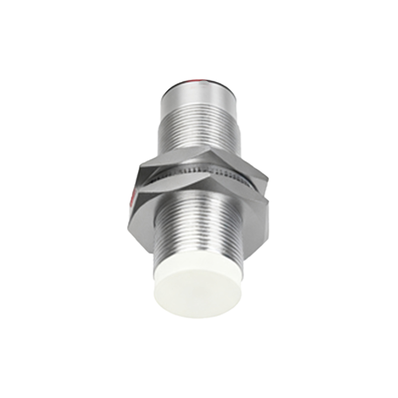
Beyond the core sensing circuitry, a comprehensive design schematic incorporates several universal blocks. The power supply section must include reverse polarity protection, often a series diode, and voltage regulation to ensure stable operation across a wide input range (e.g., 10-30V DC). Surge protection devices like Transient Voltage Suppression (TVS) diodes or metal-oxide varistors (MOVs) are essential for guarding against voltage spikes in industrial settings. The output stage schematic clearly defines the switching logic (normally open/closed), the type of output (2-wire, 3-wire NPN/PNP, or 4-wire analog), and the inclusion of a status LED with its current-limiting resistor. For advanced sensors, the schematic will integrate a microcontroller unit (MCU) for programmable functions like adjustable hysteresis, time delays, and diagnostic outputs like IO-Link communication interfaces.
A critical aspect of the schematic is the definition of electrical characteristics: the residual current (for 2-wire AC/DC types), leakage current, voltage drop, and maximum load current. These are not afterthoughts but are integral to the component selection and circuit design. Furthermore, the physical layout of the PCB, hinted at in the schematic by component placement notes, is vital for noise immunity. Proper grounding strategies, separation of analog and digital grounds, and short, direct traces for the oscillator section are imperative for stable performance.
In conclusion, a proximity switch sensor design schematic is far more than a simple connection diagram. It is a blueprint that balances electromagnetic theory, analog circuit design, and practical industrial requirements. A well-crafted schematic anticipates environmental challenges, ensures operational safety, and defines the precise performance envelope of the sensor. Mastery of these design principles allows engineers to select, integrate, and troubleshoot these devices effectively, ensuring robust and reliable automation solutions.