Proximity sensors are essential components in modern industrial automation, enabling non-contact detection of objects within a specific range. Their electrical schematics provide a clear blueprint of how these devices function, detailing the connections and components that facilitate reliable operation. This article delves into the electrical principles behind common types of proximity sensors, including inductive, capacitive, and photoelectric variants, explaining their schematic representations and practical applications.
At the core of an inductive proximity sensor's schematic is an oscillator circuit that generates a high-frequency electromagnetic field. When a metallic object enters this field, eddy currents are induced, causing a change in the oscillator's amplitude. This change is detected by a threshold circuit, which then triggers an output switch—typically a solid-state transistor or relay. The schematic illustrates key components such as the coil (L), oscillator IC, demodulator, and output driver, along with power supply connections (usually 10-30V DC). Wiring diagrams often show three terminals: positive (V+), negative (V-), and output (OUT), with protective elements like diodes and resistors to prevent voltage spikes.
Capacitive proximity sensors, designed to detect both metallic and non-metallic materials, feature a slightly different schematic. Their circuit includes a capacitor formed by the sensor's electrode and the target object. Changes in capacitance alter the oscillation frequency in an RC or LC circuit, which is monitored by a comparator. The schematic highlights components like the sensing electrode, oscillator, and signal conditioner, with adjustments for sensitivity often via a potentiometer. These sensors are commonly used in level detection or material handling, and their schematics emphasize shielding to reduce false triggers from environmental interference.
Photoelectric proximity sensors rely on optical principles, with schematics divided into emitter and receiver sections. The emitter circuit contains an LED (often infrared) driven by a constant current source, while the receiver includes a phototransistor or photodiode amplifier. When an object interrupts or reflects the light beam, the receiver's output changes state. Schematics detail components such as operational amplifiers for signal processing, filters to reject ambient light, and output stages compatible with PLC inputs. Wiring configurations vary for through-beam, retro-reflective, and diffuse models, each with specific connection requirements.
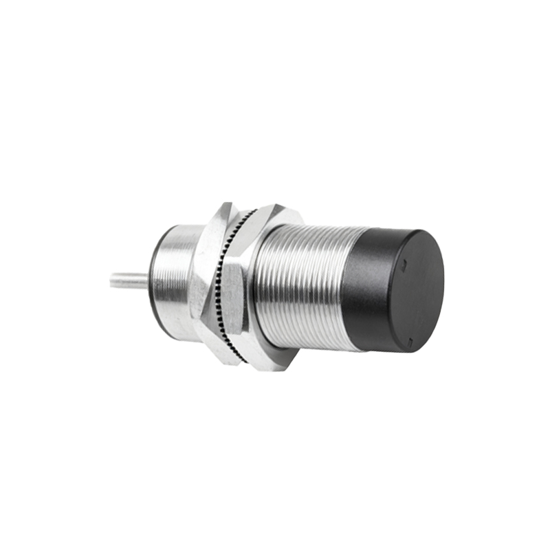
Understanding these schematics is crucial for troubleshooting and integration. For instance, inductive sensors may include short-circuit and reverse polarity protection in their design, as shown by diodes and fuses in the diagram. Capacitive sensors often incorporate guard rings in their layout to focus the sensing field. Photoelectric schematics might feature modulation/demodulation circuits to enhance noise immunity. Engineers must also consider load connections—whether NPN (sinking) or PNP (sourcing)—as depicted in the output stage of the schematic.
In practice, reading a proximity sensor schematic involves identifying power requirements, output types, and diagnostic indicators (like LED status lights). For example, a typical DC sensor schematic shows V+ and V- pins with an output transistor switching the load to ground (NPN) or positive rail (PNP). Analog output variants include additional components for signal linearization. Always refer to manufacturer datasheets for precise details, as schematics can vary based on design and application.
By mastering these electrical blueprints, professionals can optimize sensor selection, ensure proper installation, and maintain system efficiency in automation projects. Whether for conveyor systems, safety interlocks, or inventory management, proximity sensors' schematics reveal the engineering ingenuity behind their seamless operation.